




05 Aug Vibratory Finishing Capacity CNC Parts
Vibratory finishing capacity for CNC parts is one of the most frequently underestimated variables in mass finishing process planning. Incorrect batch sizing leads to media lodging, inconsistent deburring, surface damage on finished parts, and unpredictable cycle times. Whether the goal is edge rounding, deburring, or pre-polish preparation, accurate capacity calculation directly determines whether the process delivers repeatable results at production scale.
In This Article
Why Batch Capacity Calculation Matters for CNC Parts
CNC machined parts present a specific challenge for vibratory finishing because their geometry varies significantly across part families. Turned shafts, milled housings, drilled plates, and tapped brackets all behave differently inside a vibratory bowl. Unlike stamped or cast parts that tend to have simpler profiles, CNC parts often have internal channels, threaded features, and tight tolerances that respond poorly to both underloading and overloading conditions.
Underloading reduces the contact frequency between media and parts, which results in longer cycle times and uneven deburring. Overloading restricts media movement, causes part-on-part contact, and increases the risk of surface damage, particularly on aluminum and stainless steel components where cosmetic requirements are strict. Both conditions create process inconsistency that is difficult to diagnose without first reviewing the loading ratio.
Core Loading Ratio Principle
The fundamental rule in vibratory finishing is that media must always form the majority of the working volume. The standard engineering guideline is that media should occupy between 50 and 70 percent of the machine’s usable working volume, with parts filling the remaining portion. This ratio ensures that every part is surrounded by media at all times and that the vibratory motion can generate consistent part-media contact throughout the batch.
For CNC parts specifically, the media-to-part ratio by volume is typically set between 3:1 and 5:1 depending on part geometry and surface requirement. Simple turned parts with open geometry can tolerate a lower media volume, while complex milled parts with pockets, holes, and undercuts require a higher media ratio to maintain contact in all areas. Parts with deep internal features may require dedicated process testing to confirm adequate media access and prevent lodging.
Step-by-Step Batch Capacity Calculation
Calculating the correct batch size for vibratory finishing of CNC parts requires working through several sequential variables. The following process covers the key calculation steps used in industrial practice.
- Determine the machine’s gross working volume in liters. This is the total internal bowl or trough volume as specified by the manufacturer. For KAYAKOCVIB KVM circular vibratory finishing machines, this value is stated per model in the technical datasheet.
- Apply the usable volume factor. Not all of the gross volume is effectively used during operation because the vibratory motion creates a toroidal flow where the upper central zone has lower contact density. A practical usable volume factor is typically 80 to 85 percent of gross volume.
- Calculate the media volume. Apply the target media fill percentage, typically 55 to 65 percent of usable volume for most CNC part applications. This gives the media volume in liters.
- Calculate the available part volume. Subtract the media volume from the usable volume. The remaining volume is available for parts.
- Estimate part volume per piece. For simple geometries, use the bounding box volume multiplied by a fill factor. Typical fill factors range from 0.3 for complex milled housings to 0.7 for solid cylindrical turned parts. For irregular parts, water displacement measurement provides the most accurate individual part volume.
- Calculate the maximum number of parts per batch. Divide the available part volume by the estimated part volume per piece. Apply a safety margin of 10 to 15 percent reduction to account for part orientation variation and motion dynamics inside the machine.
This calculation gives the target batch size as a starting point. Actual validation requires a trial run to confirm media movement, part separation, and surface result before committing to production parameters.
Machine Type and Its Effect on Usable Capacity
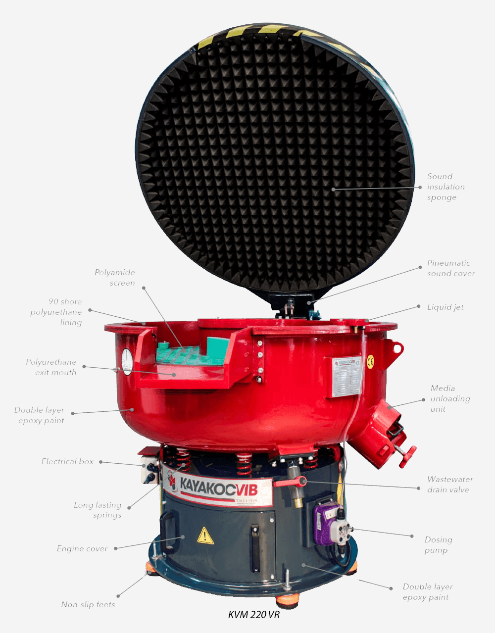
Machine geometry significantly influences effective batch capacity for CNC parts. Circular vibratory machines, such as the KVM series, generate a toroidal motion pattern that works well for small to medium CNC parts with moderate geometry complexity. The circular bowl allows continuous part circulation without manual intervention, making it suitable for batch production of turned shafts, milled inserts, and threaded fasteners.
Trough vibratory machines, such as the TVM series, provide a linear flow pattern that is more suitable for longer CNC parts, such as guide rails, spindle housings, or elongated brackets, where a circular bowl would cause parts to stack or bridge. Trough machines generally have lower effective media-to-part contact frequency per unit of time compared to circular machines, which may require longer cycle times to achieve the same surface result.
Centrifugal disc finishing machines, such as the KSM series, operate at significantly higher process intensity and are capable of achieving equivalent surface results in a fraction of the cycle time compared to vibratory machines. However, their working volume per machine is smaller, which makes capacity planning per batch more constrained. For high-precision CNC parts with tight Ra requirements, centrifugal disc machines are often preferred despite the smaller batch size, because the process intensity and media contact uniformity are substantially higher.
Common Batch Capacity Calculation Errors
Several recurring errors in vibratory finishing capacity planning for CNC parts lead to poor process results and difficult troubleshooting situations.
Using gross machine volume instead of usable volume is the most common mistake. Manufacturers sometimes load directly to the rated gross volume, which causes media to overflow during operation and reduces the toroidal flow pattern. The result is reduced media-to-part contact, longer cycle times, and uneven deburring across the batch.
Ignoring part geometry when estimating part volume leads to significant calculation errors. Assuming that a complex milled housing occupies the same volume fraction as a solid turned part produces incorrect batch sizes. Complex parts occupy more spatial volume relative to their actual material volume because of cavities, pockets, and irregular profiles.
Mixing parts of different sizes or geometries in the same batch without adjusting the media ratio is another frequent source of process inconsistency. When large and small parts are loaded together, the small parts tend to migrate under the media layer and receive less contact, while large parts may experience part-on-part contact at the surface of the batch. If mixed batches are unavoidable, a higher media ratio and longer cycle time are needed to compensate.
Neglecting to account for media wear over time causes gradual batch capacity drift. As ceramic or plastic media wears, individual piece dimensions decrease, and the effective media volume per charge decreases over time. Regular media top-up or replacement schedules should be established based on measured media consumption rates in production.
Part Material and Geometry Considerations
Material selection directly affects both media choice and loading ratio requirements. For steel and stainless steel CNC parts with machining burrs, ceramic media with cutting action is typically required. Higher media-to-part ratios support aggressive deburring without part damage. For aluminum CNC parts, plastic media is generally preferred because aluminum is softer and more sensitive to surface marking from ceramic contact, particularly at higher batch densities.
Parts with small holes, slots, or undercut features require specific attention during capacity planning because media lodging risk increases when part density in the batch is too high. When parts are tightly packed, media pieces are more likely to become trapped in internal features under the weight and motion of surrounding parts. A lower part-to-machine-volume ratio reduces lodging risk by allowing more freedom of movement and reducing the compression force on individual parts during the vibratory cycle.
Wall thickness and edge fragility also influence the maximum safe loading density. Thin-walled aluminum or titanium CNC parts can deform or chip if part-on-part contact occurs during the batch process. For these applications, a conservative media-to-part ratio of 5:1 or higher is recommended, and process intensity settings on the machine should be adjusted to reduce amplitude if the material is particularly sensitive.
Optimization Checklist for Batch Capacity Validation
Once initial capacity calculations are complete, a structured validation process helps confirm that the batch configuration delivers acceptable results before full production release. The following checklist covers the key validation points used in industrial CNC finishing applications.
- Confirm media fill level by measuring actual media volume before loading parts, not by estimating from fill height alone.
- Run a short trial cycle of 10 to 15 minutes and stop the machine to inspect part distribution. Parts should be uniformly distributed within the media mass without clustering at the bowl wall or center.
- Check for media lodging in all feature types present on the CNC part, including threaded holes, cross-drilled passages, slots, and undercuts.
- Measure surface condition of trial parts using Ra measurement if required, or by visual inspection against reference standards.
- Check for part-on-part contact marks, edge chipping, or surface marring, particularly on aluminum and stainless steel parts.
- Confirm that media is moving freely across the full bowl surface without dead zones or stagnant areas at the batch loading level.
- Run a full-length trial cycle and re-inspect parts at end of cycle before approving the batch parameters for production.
Process Parameters That Interact with Batch Capacity
Batch capacity does not exist in isolation. Several process parameters interact directly with batch size and affect whether the calculated capacity produces the intended result.
| Parameter | Effect on Batch Performance | Adjustment Direction for CNC Parts |
|---|---|---|
| Vibratory amplitude | Controls media agitation intensity and part circulation speed | Reduce for thin-walled or precision parts; increase for heavy burr removal |
| Compound flow rate | Affects cutting action, surface condition, and media cleaning | Match compound type to material; increase flow rate if media glazes during production |
| Water flow rate | Controls compound dilution and debris removal from the bowl | Maintain consistent flow; insufficient water causes compound buildup and reduced cutting |
| Cycle time | Determines total media-part contact exposure | Extend cycle time when part density is near the upper limit; reduce when overprocessing occurs |
| Media size and shape | Determines access to part features and contact surface area per piece | Select smaller media for parts with narrow features; larger media for open geometries |
Adjusting any one of these parameters without rechecking the batch capacity can shift the process outside its validated window. For example, increasing amplitude on an already full batch can accelerate part-on-part contact and increase surface marking risk, even if the loading ratio was correctly calculated at the standard amplitude setting.
Frequently Asked Questions
What is the recommended media-to-part ratio for CNC machined parts in vibratory finishing?
For most CNC part applications, a media-to-part volume ratio between 3:1 and 5:1 is recommended. Complex geometries with internal features, pockets, or thin walls require ratios closer to 5:1. Simple turned or cylindrical parts can work at 3:1. Actual ratios should be confirmed through trial runs before production release.
How do I calculate the maximum number of parts per batch in a vibratory machine?
Start with the machine’s gross working volume, apply a usable volume factor of 80 to 85 percent, allocate 55 to 65 percent of usable volume to media, and divide the remaining volume by the estimated volume per part. Apply a 10 to 15 percent safety reduction to the result. Validate the calculated batch size with a trial run before committing to production.
Can aluminum and steel CNC parts be processed in the same batch?
Mixing aluminum and steel CNC parts in the same batch is generally not recommended. The different material hardnesses require different media types and compound chemistry. Steel parts processed with ceramic media can mark aluminum surfaces, and the surface quality results for both materials will be compromised if processed together. Separate batches with appropriate media and compound for each material are required.
What causes media lodging in CNC parts during vibratory finishing?
Media lodging occurs when media pieces become trapped in holes, slots, or undercuts during the finishing cycle. The primary causes are oversized media relative to the feature opening, excessive part density in the batch, and insufficient media movement due to overloading. Selecting media with a minimum dimension larger than the largest internal feature opening, and reducing batch density, significantly reduces lodging risk.
Related Machine and Process Resources
Related Video Demonstration
Conclusion
Accurate vibratory finishing capacity calculation for CNC parts requires combining machine volume data, part geometry analysis, media selection logic, and a structured validation process. The calculations themselves are straightforward, but the most common production problems arise when loading ratios are estimated rather than calculated, or when batch parameters are transferred from one part family to another without adjustment. Applying the correct media-to-part ratio, validating with trial runs, and tracking media wear over time provides the process stability needed for consistent surface results across production shifts. For operations running mixed CNC part families, separate capacity calculations per part type and per machine model are the most reliable path to sustained process control.
Sorry, the comment form is closed at this time.