



05 Aug CNC Burr Removal
CNC burr removal is a production requirement that affects part function, assembly clearance, operator safety, and downstream coating adhesion. Burrs are an unavoidable consequence of most CNC machining operations including milling, turning, drilling, and tapping. Understanding the type, location, and size of the burr is a prerequisite for selecting the correct deburring process, machine, and media combination. Without this classification step, manufacturers risk either insufficient material removal or surface damage to precision machined features.
In This Article
How CNC Machining Creates Burrs
Burrs form when a cutting tool exits a workpiece surface, forcing material plastically beyond the nominal part edge rather than cleanly shearing it. The resulting projection can be thin and flexible, hard and rigid, or layered depending on the base material, tool condition, cutting speed, and feed rate. Aluminum alloys tend to produce long, ductile burrs with some stickiness. Hardened steel and stainless steel produce shorter but harder burrs that require more aggressive cutting action to remove. Cast iron typically produces brittle burrs that break more easily but generate fine abrasive particles during finishing.
Burr geometry also varies by operation. Drilling exit burrs appear on the breakthrough face. Milling edge burrs follow the tool path direction. Cross-hole intersections create internal burrs that are among the most difficult to reach. Tapped holes can retain spiral thread burrs that interfere with fastener engagement. Recognizing these patterns early determines whether a vibratory finishing process alone is sufficient or whether a combination of operations is required.
Burr Type Classification for Process Selection
From a process engineering perspective, burrs on CNC machined parts are commonly grouped into four categories based on their mechanical behavior and the finishing energy required to remove them.
| Burr Category | Typical Source | Material Behavior | Removal Approach |
|---|---|---|---|
| Rollover burr | Milling exit edge | Thin, flexible, folds over edge | Low-to-medium intensity vibratory finishing |
| Poisson burr | Drilling, turning | Lateral material displacement, wider base | Medium intensity, abrasive media |
| Tear burr | Worn tooling, interrupted cuts | Irregular, partly detached, rough profile | High intensity or pre-processing required |
| Cut-off burr | Parting, sawing | Thick stub or projection | Machining or grinding before finishing |
This classification is not exhaustive but covers the most common cases in CNC machined steel, stainless steel, and aluminum production. Large cut-off burrs or heavy tear burrs on hardened materials may require mechanical pre-processing before mass finishing equipment can achieve a clean edge. Attempting to remove very large burrs purely in vibratory equipment risks excessive cycle times, increased media wear, and inconsistent results across a batch.
Recommended Process Route for CNC Parts
A practical CNC burr removal process route depends on the burr type identified above, the part material, the required edge condition after deburring, and the production volume. For most CNC machined aluminum and steel parts with standard rollover or Poisson burrs, the following sequence covers the common industrial requirement.
- Inspect incoming parts for burr size, location, and surface condition. Parts with oversized burrs or sharp gate remnants may require manual or mechanical pre-processing before batch finishing.
- Select media type and size based on part geometry. Media must reach all deburring zones without lodging in holes, slots, or recesses. Media size should be at least 20 to 30 percent larger than the smallest hole or opening on the part.
- Load the finishing machine at the correct fill ratio. Overfilling reduces media movement and deburring efficiency. Underfilling increases part-to-part impact risk for delicate components.
- Set process parameters including vibration amplitude, cycle time, compound dosing, and water flow rate. For initial trials, start with the media manufacturer’s recommended baseline and adjust based on sample results.
- Run a sample batch and inspect for burr removal completeness, edge radius consistency, and surface condition. Adjust parameters before committing to full production.
- After finishing, separate parts from media using a separator unit. Wet parts should be rinsed and dried promptly to prevent water staining, especially on aluminum and bare steel.
- Inspect finished parts against the required edge condition standard. Document the confirmed process parameters for production release.
Machine Selection for CNC Burr Removal
Machine type selection is driven by part size, geometry, material, required surface quality, and production volume. Four machine types are commonly used for CNC machined part deburring.
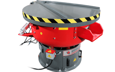
Circular vibratory finishing machines are the most widely used platform for general CNC burr removal. They handle mixed batch sizes efficiently, accept a broad range of media types, and can be integrated with separators, washing units, and dryers. A circular vibratory machine such as the KAYAKOCVIB KVM series is well suited to small and medium CNC parts in steel, stainless steel, and aluminum where standard edge deburring and light surface improvement are required.
Trough vibratory finishing machines are preferred for longer parts, larger components, or parts where circular bowl geometry creates part-to-part collision risk. The linear media flow in a trough machine provides more controlled movement for asymmetric or elongated parts.
Centrifugal disc finishing machines operate at higher finishing intensity and shorter cycle times than standard vibratory machines. They are applicable to small high-precision CNC parts where rapid burr removal with tight edge radius control is required. The KAYAKOCVIB KSM series is an example of this machine type used for precision aluminum and steel components where cycle time is a production constraint.
Drag finishing machines hold parts individually in fixtures and drag them through a media mass at controlled depth and speed. This approach is used for high-value CNC parts, cutting tools, and precision components where uniform edge rounding, defined Ra improvement, and individual part traceability are required. The KAYAKOCVIB DRG series represents this category for controlled high-end finishing applications.
Media and Compound Selection by Material
Media and compound selection is a direct function of the base material being finished. Incorrect media hardness or compound chemistry can damage part surfaces, produce inconsistent edge conditions, or fail to remove the target burr within a practical cycle time.
For aluminum CNC parts, plastic media is generally preferred. Aluminum is a relatively soft and ductile material that can be scratched or over-cut by ceramic media unless a gentle cutting action is specifically required. Plastic media in pyramid or cylinder shapes provides sufficient cutting energy for aluminum burr removal while reducing the risk of surface damage. A deburring and polishing liquid such as KAYAKOCVIB 085 compound is a suitable chemistry for aluminum wet finishing. For parts with machining oil or coolant contamination, 028-S degreasing liquid is used as a pre-clean or combined with the finishing cycle.
For steel and stainless steel CNC parts, ceramic media is generally preferred. These harder materials require stronger abrasive cutting action to remove burrs efficiently. Ceramic media in preformed shapes such as triangles, cylinders, or wedges is available in various abrasive grades from fast-cut to burnishing. KAYAKOCVIB 943 deburring and polishing liquid is a typical compound for steel wet finishing, with 028-S degreasing liquid applied when coolant or oil contamination is present.
Mixed batches of aluminum and steel parts should generally be avoided. The different densities and hardness levels lead to uneven finishing results and potential surface damage to softer parts from harder part-to-part contact.
Process Parameters That Control Edge Quality
Several process variables directly affect the final edge condition and surface quality after CNC burr removal. These parameters must be set consistently and validated through sample testing before production release.
Vibration amplitude controls the intensity of media contact with part surfaces. Higher amplitude increases cutting rate and is useful for harder burrs, but can cause edge over-rounding or surface damage on thin-walled aluminum parts. Amplitude is typically adjustable on most industrial vibratory machines through eccentric weight configuration.
Cycle time determines how much material is removed and the final edge radius achieved. Longer cycles produce more rounding. For functional deburring with minimal geometry change, cycle times must be controlled carefully and confirmed against part tolerances.
Compound dosing rate affects lubrication, cooling, cutting chemistry, and surface brightness. Insufficient compound leads to excessive media wear, part staining, and reduced cutting efficiency. Excess compound can leave surface residue or cause foam buildup in the machine bowl.
Media-to-part ratio and machine fill level affect how freely parts move through the media mass. A commonly used fill level in circular vibratory machines is approximately 80 to 90 percent of the bowl working volume, though the optimal level depends on part size and machine design. This should be confirmed through machine-specific setup and process testing.
Washing and Drying After Wet Finishing
Wet vibratory finishing leaves parts coated with a compound-water mixture containing fine abrasive particles, swarf, and metallic debris. Immediate rinsing after separation is important for aluminum parts and bare steel parts that are susceptible to water staining or flash corrosion. Parts should be rinsed with clean water, then dried promptly in a centrifugal or vibrating dryer using dry drying media such as corn cob or walnut shell granules.
For CNC parts with complex geometries, blind holes, or recessed features where pooled water is difficult to remove, pressure washing or ultrasonic cleaning may be required after finishing to ensure complete cleanliness before inspection or coating. In automated finishing lines, washing and drying stages are integrated into a continuous flow sequence to maintain part cleanliness and process consistency without manual handling between steps.
Quality Control Points After Deburring
Confirming the result of CNC burr removal requires inspection at defined control points. Visual inspection under controlled lighting or magnification is the baseline method. For functional applications, edge radius measurement using contact profilometry or optical measurement confirms that the required edge condition has been achieved without over-rounding critical geometry.
Surface roughness measurement using Ra values indicates whether the media cutting action has improved or maintained the machined surface texture. In most vibratory deburring applications, light surface improvement is a secondary benefit. However, if Ra improvement is a primary objective alongside burr removal, a multi-stage process using progressively finer media or a burnishing stage may be required.
Parts should also be inspected for media lodging, especially in cross-drilled holes, tapped features, or narrow slots. Media lodging is a process defect that can cause assembly problems or component failure. If lodging is observed during sample testing, media size must be increased or the process route must be modified before production release.
Frequently Asked Questions
Can vibratory finishing remove all CNC burr types?
Vibratory finishing is effective for rollover, Poisson, and light tear burrs on most CNC machined parts. Very large tear burrs, thick cut-off stubs, or burrs on hardened materials may require mechanical pre-processing before vibratory finishing can achieve a clean edge. Process capability should always be confirmed through sample testing before production commitment.
How do I prevent media lodging in small holes?
Select media with a minimum size at least 20 to 30 percent larger than the smallest opening on the part. For parts with very small holes or narrow slots, consult with the media supplier for a geometry-specific recommendation. In some cases, plugging or masking small holes before finishing is the only practical solution.
Should aluminum and steel CNC parts be deburred in the same batch?
Generally, aluminum and steel parts should not be mixed in the same finishing batch. The difference in density and hardness leads to uneven cutting action, and harder steel parts can damage softer aluminum surfaces during part-to-part contact. Separate batches with material-specific media and compound are the standard industrial practice.
How long does a typical vibratory deburring cycle take for CNC parts?
Cycle times vary widely depending on burr size, material, media type, machine intensity, and required edge condition. Light deburring of aluminum parts with plastic media may be completed in 15 to 30 minutes in many industrial applications. Steel parts with harder burrs and ceramic media may require 30 to 90 minutes or more. Actual cycle time must be validated through sample testing for each specific application.
Related Process Equipment
Related Video Demonstration
Conclusion
Effective CNC burr removal requires a structured approach that starts with burr type classification and ends with validated process parameters confirmed through sample testing. Machine selection, media type, compound chemistry, and process settings must be matched to the specific part material, geometry, and production volume. For aluminum CNC parts, plastic media and appropriate deburring chemistry provide the right balance of cutting action and surface protection. For steel and stainless steel parts, ceramic media with suitable compound delivers the higher abrasive energy required. Circular vibratory machines cover the majority of standard CNC deburring applications, while centrifugal disc machines and drag finishing systems serve precision and high-value parts where tighter edge control is required. Regardless of machine type, process validation through sample batches before production release remains the only reliable path to consistent edge quality and surface condition.
Sorry, the comment form is closed at this time.