


03 Aug Automatic Loading Vibratory Finishing
Automatic loading vibratory finishing refers to the integration of automated part feeding, loading, and unloading systems with vibratory finishing machines to create continuous or semi-continuous production workflows. Rather than relying on manual batch loading, these systems use conveyors, hoppers, bowl feeders, robotic arms, or elevator transfer units to move parts into and out of the finishing machine without direct operator intervention. The decision to automate this stage of the finishing process depends on production volume, part geometry, part fragility, cycle time requirements, and the degree of traceability or process consistency required downstream.
In This Article
When Automatic Loading Becomes a Practical Requirement
In low-volume or prototype environments, manual loading of vibratory finishing machines is entirely practical. An operator loads a batch of parts, adds the correct media and compound charge, runs the machine, and unloads when the cycle is complete. This approach is flexible and requires minimal capital investment.
As production volume increases, the economics of manual loading shift. If a finishing machine runs multiple cycles per shift across five or more days per week, manual loading becomes a labor bottleneck. Operator availability, loading consistency, and cycle time repeatability all become variables that affect surface quality and throughput. At this point, automatic loading vibratory finishing configurations begin to show clear advantages in labor efficiency, process repeatability, and integration with upstream and downstream production equipment.
Automatic loading also becomes relevant when parts arrive directly from CNC machining centers, stamping presses, or die casting machines on conveyors, and the production planner wants to connect those upstream processes directly to the finishing stage without accumulation buffers or manual transfers.
Main Selection Criteria for Loading System Type
Selecting the right automatic loading configuration for a vibratory finishing line requires evaluating several interdependent factors. There is no single universal loading system that fits every application. The following criteria drive the selection decision.
Part geometry is the primary filter. Flat stamped parts, small cylindrical fasteners, turned CNC components, and irregular castings each require different feeding logic. Parts that can roll or slide consistently are well suited to vibratory bowl feeders or chute systems. Parts with complex geometry or thin features may require robotic pick-and-place or orientated conveyor loading to avoid damage during transfer.
Part fragility and surface condition before finishing must be assessed carefully. If parts arrive with sharp edges, burrs, or hard points that could damage adjacent parts during bulk feeding, the loading system must account for this. Bulk feeding of very thin-walled or soft aluminum parts at high drop heights can cause pre-finish damage that the vibratory cycle cannot correct.
Batch size versus continuous flow is another critical selection factor. Circular vibratory machines typically operate in batch mode, where a defined volume of parts and media is loaded per cycle. Trough vibratory machines can be configured for through-feed or continuous flow operation, where parts enter one end and exit the other during operation. The loading system design differs significantly between these two machine types.
Cycle time and synchronization with upstream equipment determines whether a buffer hopper or direct conveyor feed is required. If the upstream CNC machine produces parts faster than the vibratory finishing cycle completes, a buffer storage unit with controlled discharge is needed to prevent overloading the finishing machine.
System Types and Their Technical Logic
Several distinct automatic loading configurations are used in industrial vibratory finishing lines. Each has specific advantages depending on part characteristics and production layout.
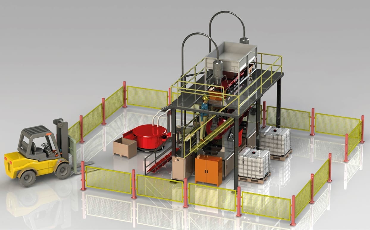
Hopper and elevator loading systems are among the most common configurations for circular vibratory machines. Parts are collected in a hopper after upstream processing and elevated by a bucket elevator or belt elevator into the vibratory machine bowl. This system suits small to medium parts such as fasteners, turned parts, and stamped components that are not sensitive to bulk handling. The elevator speed and discharge timing can be controlled to regulate the load volume per cycle.
Vibratory bowl feeder systems are used when parts require orientation before entry into the finishing machine or into a downstream process. These are more common in lines where parts exit the finishing machine and require orientation for inspection, coating, or assembly rather than at the loading stage. However, they can be used as controlled metering feeders when part geometry allows consistent orientation.
Conveyor belt loading systems are used in continuous or semi-continuous trough vibratory finishing lines. Parts travel along a flat or inclined conveyor and are fed into the trough machine inlet continuously or in controlled pulses. This configuration suits production lines where the finishing machine is placed inline between two production stages, such as between a press and a washing unit.
Robotic loading systems are used for parts that require careful placement, controlled orientation, or separation to prevent part-on-part contact during the finishing cycle. This is relevant for precision components, fragile parts, or high-value parts such as medical implants or aerospace precision components where batch loading creates unacceptable collision risk. Robotic loading is significantly more expensive and is justified only when part value or process specification demands it.
Integration with Separation, Washing, and Drying
Automatic loading vibratory finishing lines are most effective when the entire process route is integrated, not just the loading stage. After the finishing cycle completes, parts must be separated from finishing media, washed to remove compound residues, and dried before transfer to inspection, packaging, or the next production stage.
A separator machine placed after the vibratory finishing machine screens parts from media automatically. In KAYAKOCVIB automation lines, separation, washing, and drying units are connected in sequence with the vibratory machine so that parts flow through the complete process route without manual intervention between stages.
Washing systems remove compound residue, oil, and fine media particles from part surfaces after finishing. For many industrial applications, a pressure washing or spray rinsing system is sufficient. For parts with blind holes, threads, or recessed geometry, ultrasonic cleaning may be required to ensure residue-free surfaces before inspection or coating.
Drying is required before parts are transferred to packaging or coating lines. Vibratory dryers use warm air flow combined with drying media to remove surface moisture without thermal damage. For long or large parts, trough-type dryers are more appropriate than circular bowl dryers. The drying stage should be sized to match the output rate of the finishing machine so that no wet part accumulates waiting for drying capacity.
Loading System Selection Matrix
| Loading System Type | Suitable Part Types | Machine Type | Key Limitation |
|---|---|---|---|
| Hopper and Elevator | Fasteners, small turned parts, stamped parts | Circular vibratory (batch) | Not suitable for fragile or thin-walled parts |
| Belt Conveyor Feed | Flat or regular parts, medium batch flow | Trough vibratory (continuous) | Requires consistent part geometry for stable feed |
| Vibratory Bowl Feeder | Small oriented parts, controlled metering | Circular or trough, batch or continuous | Limited to parts that can be oriented by vibration |
| Robotic Loading | Precision parts, high-value parts, fragile parts | Any machine type | High capital cost, requires programming and maintenance |
| Manual Assisted Semi-Auto | Mixed or irregular parts, low volume | Any machine type | Labor dependent, lower consistency than full automation |
Process Parameters That Affect Automated Line Performance
Automating the loading stage does not automatically guarantee process consistency. Several process parameters must be controlled and validated to achieve repeatable surface quality in an automatic loading vibratory finishing configuration.
Load volume per cycle must be controlled accurately. Overloading the vibratory machine bowl reduces media-to-part contact efficiency and slows the finishing action. Underloading reduces the cushioning effect of media and can increase part-on-part contact, particularly for soft materials such as aluminum. Hopper and elevator systems should use volume or weight sensors to control the charge per cycle.
Media charge must be maintained at the correct level and replaced at defined intervals. In continuous lines, media wear must be monitored because worn media loses cutting action and changes the surface finish result. Some automated lines use continuous media addition systems to compensate for media wear between full charge replacements.
Compound dosing in automated lines is typically handled by automatic compound injection systems that deliver a controlled volume of liquid compound with the process water at defined intervals during the finishing cycle. Compound concentration directly affects deburring rate, surface brightness, and part cleanliness, so automatic dosing improves consistency compared to manual addition.
Cycle time must be validated for the specific part, material, burr condition, and required surface quality before automated production begins. Automated lines operate at fixed cycle times, so process parameters must be confirmed through sample testing before committing to a production run. Actual cycle times depend on part material, burr size, media type, compound concentration, and machine amplitude settings.
Common Configuration Errors to Avoid
Several recurring errors appear when automatic loading vibratory finishing systems are designed or commissioned without sufficient process validation.
Mixing part materials in the same automated batch is a common mistake in general manufacturing environments where multiple part types are finished on the same line. Aluminum and steel parts should not be processed together because the harder steel parts can damage the softer aluminum surfaces. Automated lines must include part segregation logic upstream to prevent mixed batches from entering the finishing machine together.
Undersizing the buffer hopper relative to the upstream production rate causes parts to back up or forces the finishing machine to run with inconsistent load volumes. The buffer capacity should be calculated based on the maximum upstream output rate and the finishing cycle time.
Neglecting the media level sensor is another common oversight. If media level in the bowl drops below the operating minimum and no alarm triggers, the machine continues running with insufficient media, leading to accelerated part-on-part contact and surface damage before the fault is detected.
Skipping the separation validation step when commissioning the automated line can result in parts passing through the separator too quickly and returning with media still in blind holes or internal features. Separator aperture size and vibration settings must be validated specifically for the part geometry and media combination used in production.
Automation Readiness Checklist
Before installing an automatic loading vibratory finishing system, the following conditions should be confirmed to support a successful integration.
- Part geometry is suitable for bulk or conveyor handling without pre-finish damage
- Upstream production rate is quantified and a buffer sizing calculation has been completed
- Media type and charge volume have been validated through sample finishing tests
- Compound dosing system and concentration range have been defined
- Separator aperture and vibration settings have been validated for the specific part and media
- Washing system capacity matches the finishing machine output rate
- Drying capacity matches the washing and finishing output rate
- Cycle time has been confirmed through sample testing, not assumed from reference data
- Part material segregation logic is in place upstream of the loading station
- Media level and compound dosing alarms are configured and tested
Frequently Asked Questions
What is the main advantage of automatic loading in vibratory finishing?
The primary advantage is repeatable process consistency combined with reduced labor cost per part. Automated loading eliminates variability in load volume, compound dosing, and cycle timing that occurs with manual batch loading, which improves surface quality consistency across high-volume production runs.
Can automatic loading systems be used with both circular and trough vibratory machines?
Yes. Hopper and elevator systems are commonly used with circular vibratory batch machines. Belt conveyor feed systems are typically used with trough vibratory machines configured for continuous or semi-continuous flow. The specific loading configuration must match the machine type and part handling requirements.
How is media wear managed in an automated vibratory finishing line?
Media wear is managed through scheduled media additions or full media charge replacement at defined intervals based on cumulative running hours or observed cutting action. Some automated lines include continuous media top-up systems. Media level sensors provide alarms when the charge falls below the minimum operating level.
Is robotic loading always necessary for precision parts?
Not always. Robotic loading is justified when parts require controlled orientation, separation to prevent contact damage, or when part value does not allow any risk of handling damage. For many precision parts that can tolerate bulk handling with appropriate media cushioning, a hopper and elevator system with validated load volume control is sufficient.
Related Process Equipment
Related Video Demonstration
Conclusion
Selecting and configuring an automatic loading vibratory finishing system requires a structured evaluation of part geometry, material, production volume, machine type, and downstream process requirements. There is no single loading configuration that is universally optimal. The decision should follow the selection criteria and configuration logic described in this guide, supported by sample testing and process validation before full production commitment. When designed correctly, automatic loading vibratory finishing lines deliver consistent surface quality, reduced labor dependency, and reliable integration with upstream and downstream production stages across industries including CNC machining, automotive, fasteners, aerospace, and medical manufacturing.
Sorry, the comment form is closed at this time.