
24 Jun Size Surface Finishing Line
To correctly size a surface finishing line, engineers must evaluate production volume, part geometry, material, burr condition, required surface quality, and downstream process integration before selecting any machine or configuring any line layout. Undersizing leads to production bottlenecks; oversizing increases capital and operating costs without process benefit. This reference provides a structured technical framework for calculating finishing capacity and selecting the correct machine configuration for a given production environment.
In This Article
Core Variables That Define Line Capacity
Surface finishing line capacity is not defined by machine size alone. It is a function of several interacting variables that must be evaluated together before any equipment decision is made.
The primary variables are: part volume per hour or per shift, part geometry and bulk density, required cycle time per batch or per part, media-to-part loading ratio, machine working volume, separation time, and drying or washing time if these steps are required. Each of these variables influences the others, and changing one typically requires recalculating the rest.
Cycle time is particularly important. For vibratory finishing, typical deburring cycles for steel CNC parts range from 20 to 90 minutes depending on burr size, media aggressiveness, and required surface roughness. For centrifugal disc finishing of small precision parts, cycle times are shorter, commonly between 5 and 20 minutes. These ranges are application-dependent and must be validated through sample testing before line sizing is finalized.
Production Volume Calculation Method
The fundamental sizing calculation starts with the required output per shift and works backward through cycle time to determine the number of machine batches needed per shift, then the required total machine working volume.
A simplified capacity calculation follows this logic:
- Define the required part output per shift in kilograms or pieces.
- Determine the maximum part load per batch based on the machine working volume and the recommended media-to-part ratio, typically between 1:3 and 1:5 by volume for vibratory finishing.
- Divide the available processing time per shift by the total cycle time per batch, including loading, separation, and unloading time.
- Calculate how many batches are achievable per shift.
- Compare achievable output per shift with required output. If insufficient, increase machine size, add a second machine, or evaluate continuous processing options.
For example, if a production facility needs to finish 800 kg of steel CNC parts per eight-hour shift, and each batch processes 120 kg of parts with a 45-minute finishing cycle plus 10 minutes for separation and unloading, approximately eight batches are achievable per shift, giving a capacity of 960 kg per shift. This provides a small buffer. If cycle time increases due to a heavier burr specification, the buffer shrinks and must be recalculated.
Machine Selection Logic for Finishing Line Sizing
Once the capacity requirement is established, machine type selection depends on part geometry, part size, and process intensity requirements. Different machine types suit different production conditions.
| Machine Type | Suitable Parts | Typical Working Volume | Cycle Time Range |
|---|---|---|---|
| KVM Circular Vibratory | Small to medium parts, CNC, stamped, fasteners, die cast | 50 to 1500 liters | 20 to 90 minutes |
| KSM Centrifugal Disc | Small precision parts, medical, aerospace, short cycles | 5 to 100 liters | 5 to 20 minutes |
| TVM Trough Vibratory | Long, large, or delicate parts | 100 to 3000 liters | 30 to 120 minutes |
For high-volume production of small to medium steel or aluminum CNC parts, a circular vibratory machine such as the KAYAKOCVIB KVM series is a common configuration. The KVM series offers a range of bowl volumes that can be matched to calculated batch size requirements. When output demands exceed what a single machine can deliver within one shift, a second parallel machine is typically more practical than moving to a very large machine that introduces handling complexity.
For small high-precision parts where surface quality requirements are tight and cycle time must be minimized, centrifugal disc finishing with a KAYAKOCVIB KSM series machine provides significantly higher process intensity than vibratory finishing. The shorter cycle time per batch allows more batches per shift with a smaller machine footprint, which can be advantageous when floor space is constrained.
Media-to-Part Ratio and Loading Discipline
Correct media-to-part loading ratio is one of the most frequently underestimated factors when sizing a finishing line. If the ratio is not maintained consistently, cycle time and surface quality results will vary between batches, making reliable capacity planning impossible.
For vibratory finishing with ceramic media on steel parts, a media-to-part volume ratio of approximately 3:1 to 4:1 is typical. For plastic media on aluminum or zamak parts, a similar ratio applies, but process intensity must be set lower to avoid surface damage. When parts are loaded too densely relative to media, inter-part contact increases and part-on-part damage risk rises. When parts are too sparse in the media bed, finishing action becomes inefficient and cycle time extends unnecessarily.
Media selection must be matched to the base material. For steel and stainless steel parts, ceramic media is generally preferred because it delivers sufficient cutting force for effective deburring and edge rounding. For aluminum and zamak parts, plastic media is the more appropriate choice due to the softer and more damage-sensitive nature of these materials. Mixing aluminum and steel parts in the same batch is not recommended because media aggressiveness optimized for one material will typically be incorrect for the other.
Separation, Washing, and Drying in Line Sizing
A finishing line is not defined by the finishing machine alone. Separation, washing, and drying steps are part of the total cycle time calculation and must be included when sizing the line for production volume.
After wet vibratory finishing, parts and media must be separated. For most small to medium parts, this is done using a vibratory separator. Separation time depends on part geometry, part size, and the risk of media lodging in part cavities or holes. For simple parts, separation is fast. For complex geometries, separation may require additional attention and time allowance in the cycle plan.
If parts require washing after finishing to remove compound residue, chips, or polishing paste, a washing step adds to the total line cycle. In automated finishing lines, washing, separation, and drying units can be integrated as continuous downstream stations, reducing manual handling time and allowing the finishing machine to begin the next batch while earlier batches are being washed or dried.
Drying is required when parts must be delivered dry for inspection, packaging, or a subsequent coating or assembly operation. A vibratory dryer such as the KAYAKOCVIB DVM series can be integrated directly after separation. Drying time depends on part geometry, material, and the volume of water carried over from the finishing process. For high-volume production, drying capacity must be sized to match finishing output so that drying does not become the production bottleneck.
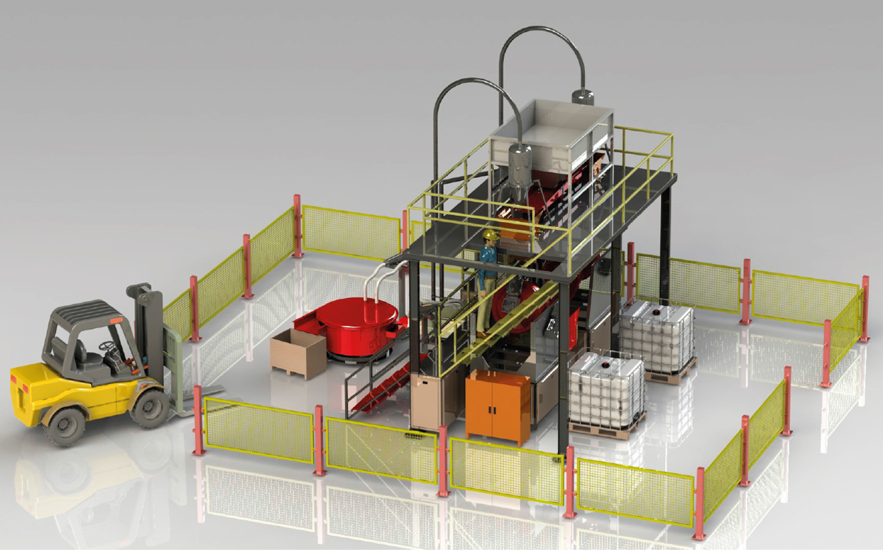
Automation Level and Line Layout
The decision to automate a finishing line must be driven by production volume, shift structure, part handling requirements, and labor cost considerations. Not all finishing applications benefit equally from automation, and the correct automation level must be matched to the actual production context.
At low to moderate volumes, a semi-automated line where parts are loaded manually but separation and drying are integrated is often the most cost-effective configuration. At high volumes, particularly in automotive, fastener, or CNC machining production, full automation with conveyor loading, automatic dosing of compound and water, integrated separation, washing, and drying, and automated part discharge reduces cycle variability and labor dependency.
When sizing a surface finishing line for automation, process engineers must also define the control architecture. Consistent compound dosing, water flow rate, and vibration amplitude settings are necessary for repeatable results across all batches. If these parameters vary between operators or shifts, surface quality will vary and capacity calculations based on nominal cycle times will not hold in practice.
ROI Considerations When Sizing a Finishing Line
Line sizing decisions have a direct impact on capital investment and operating cost. Oversizing a surface finishing line increases machine purchase cost, media inventory cost, compound consumption, floor space, and energy consumption without increasing throughput. Undersizing creates a production constraint that may force overtime or batch rejection when cycle targets are missed.
A practical ROI evaluation for a finishing line should include the following factors: machine purchase and installation cost, media initial fill and annual replacement cost, compound and water consumption per shift, energy cost per hour of operation, labor cost per shift depending on automation level, and the cost of scrap or rework if surface quality is not consistently achieved.
Actual payback periods depend heavily on production volume, part value, current manual finishing cost, and the degree of automation implemented. These figures must be calculated for each specific application. General industry experience suggests that high-volume automated finishing lines for automotive or fastener production can recover investment faster than low-volume specialty applications, but this requires validation with realistic production and cost data specific to each facility.
Practical Validation Before Line Release
Before a sized finishing line is released to production, process validation must confirm that the calculated cycle time delivers the required surface quality at the target production volume. Validation should include sample batch testing across the full range of expected part variants, media and compound verification, and capacity confirmation across at least one full production shift.
Surface roughness measurements, edge condition inspection, and part damage evaluation should be part of the validation protocol. If cycle time must be extended to achieve the required surface quality, the production capacity calculation must be revised accordingly. Line sizing based solely on theoretical cycle time without sample validation is a common source of capacity shortfall in production startup.
Frequently Asked Questions
What is the most important variable when sizing a surface finishing line?
Cycle time per batch is typically the most critical variable because it directly determines how many batches can be completed per shift. Cycle time must be established through sample testing, not assumed from general reference values, because it varies with burr size, material, media type, and required surface quality.
Can a single vibratory machine handle mixed part types in the same batch?
Mixed batches are possible only when parts share similar material, geometry, and finishing requirements. Mixing aluminum and steel parts in the same batch is generally not recommended because media selection optimized for one material is usually incorrect for the other. Mixed batches also complicate cycle time validation and surface quality control.
How does automation affect line capacity?
Automation primarily reduces unproductive time between batches by eliminating manual loading, unloading, and handling delays. In high-volume production, automation also improves process consistency by ensuring that compound dosing, water flow, and vibration settings remain constant across all batches and all shifts.
When should a centrifugal disc machine be chosen over a vibratory machine for capacity planning?
A centrifugal disc machine is preferred when parts are small, when cycle time must be minimized, or when surface quality requirements are tighter than standard vibratory finishing can reliably deliver. The higher process intensity of centrifugal disc machines allows more batches per shift with a smaller footprint, which can improve capacity per square meter of floor space.
Related Process Equipment
Related Video Demonstration
Conclusion
To correctly size a surface finishing line, engineers must combine production volume targets with realistic cycle time data, media loading discipline, and downstream process integration. No single machine size or type is universally correct. The right configuration depends on part geometry, material, burr condition, required surface quality, shift structure, and automation level. Theoretical capacity calculations must always be confirmed through sample testing and production validation before a line is released. A well-sized surface finishing line delivers consistent surface quality, predictable throughput, and a measurable return on the capital invested in the finishing operation.
Sorry, the comment form is closed at this time.