


02 Aug Robotic Loading Finishing Line
A robotic loading finishing line combines mechanical part handling with surface finishing process control to eliminate manual loading variability and maintain consistent throughput across deburring, polishing, and edge conditioning operations. In industries such as CNC machining, automotive, aerospace, and medical device manufacturing, manual loading introduces inconsistency in part orientation, dwell time, and process exposure that automation is specifically designed to eliminate. This article explains how robotic loading integrates with surface finishing equipment, what the process sequence looks like in practice, how machine and process parameters are controlled, and what engineers need to consider before implementing an automated finishing line.
In This Article
What Robotic Loading Means in a Finishing Context
Robotic loading in surface finishing refers to the use of industrial robots or purpose-built automation systems to load, position, transfer, and unload parts through one or more finishing machines without manual intervention at each station. The robot replaces the human operator for repetitive handling tasks while the finishing machine performs the actual surface treatment.
This is distinct from fully continuous batch processing, where parts tumble freely in a vibratory or centrifugal machine. In robotic loading applications, the robot often controls how the part enters the machine, in what orientation, and for how long it is exposed to the finishing media or tooling. The result is a deterministic process where part handling is repeatable from cycle to cycle.
Drag finishing machines, such as the KAYAKOCVIB DRG-Two Step, are a common example where robotic or programmed spindle loading is central to the process design. In drag finishing, individual parts are mounted on spindle holders and dragged through a trough of finishing media at controlled depth, speed, and rotation. Each part follows an identical process path, which is fundamentally different from free-tumbling vibratory processing.
Where the Process Starts and Ends
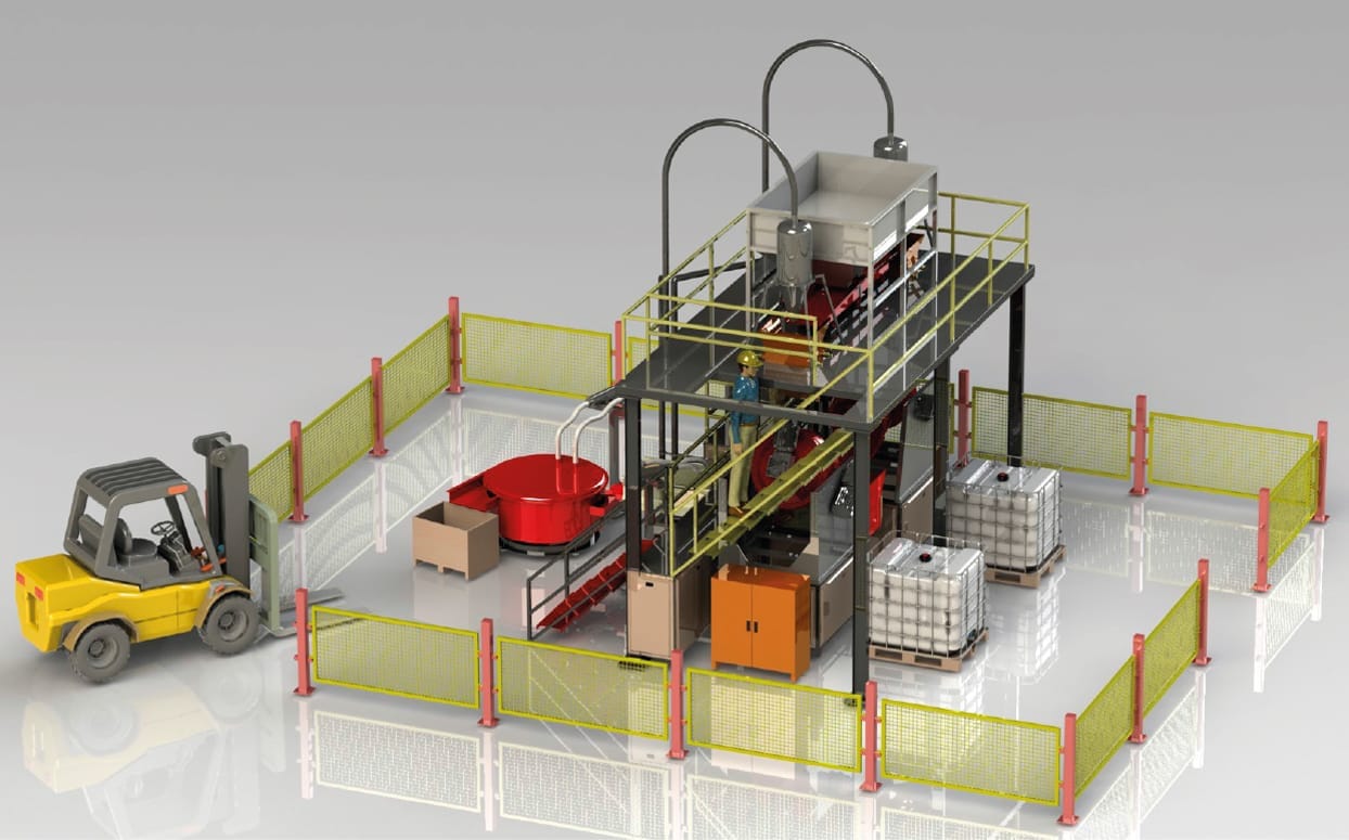
A robotic loading finishing line typically begins at a part input station where machined, stamped, cast, or otherwise pre-processed parts arrive from an upstream operation. Parts may come directly from a CNC machining center, a press, or a casting cell. At the input station, parts are either presented in fixtures, trays, or conveyors, and a robot or handling system picks them up using a gripper, magnetic pickup, or vacuum end effector selected for the part geometry and material.
The line ends at a verified output station where finished parts have passed through all required process stages, including finishing, washing, drying, and inspection if applicable. At this point, parts are either handed off to a downstream process such as coating or assembly, placed into output trays, or transferred to a conveyor for further handling.
Between input and output, the line may include one or more finishing stages, a washing station to remove finishing compound residue, a drying station, and a separation or inspection point. The robotic loading system coordinates the movement of parts through each of these stages according to a programmed sequence.
Step-by-Step Process Sequence
The following sequence describes a typical robotic loading finishing line layout for CNC machined parts requiring deburring and edge conditioning.
- Parts arrive at the input station from the upstream machining cell, presented in a fixture tray or on a conveyor. A vision system or proximity sensor confirms part presence and orientation.
- The robot arm picks the part using the appropriate end effector. For steel or stainless steel parts, a magnetic gripper may be used. For aluminum or mixed metal parts, a mechanical or vacuum gripper is more appropriate to avoid surface marking.
- The robot loads the part into the finishing machine. In a drag finishing application, the part is mounted on a spindle holder. In a vibratory application, parts may be loaded into a dedicated fixture or batch container. Machine loading confirmation is sent to the line controller.
- The finishing machine executes the programmed cycle. Parameters such as spindle speed, immersion depth, trough rotation, cycle time, compound flow rate, and media type are controlled by the machine PLC. The robot waits or performs another task during this phase.
- At cycle completion, the robot unloads the part from the finishing machine and transfers it to the washing station. Washing removes residual finishing compound, fines, and media dust from the part surface. A pressure washing or spray washing system is commonly used at this stage.
- After washing, the part moves to the drying station. Drying removes surface moisture before the part proceeds to downstream operations such as coating, packaging, or assembly. Hot air drying or centrifugal drying is typically used depending on part geometry.
- The robot or a transfer conveyor delivers the finished and dried part to the output station. An optional inspection point using vision cameras or surface profilometry equipment may verify surface condition before the part is released.
- The line controller logs the completed cycle and signals readiness for the next part. Throughput rate, alarm history, and process parameter records are stored for traceability.
Machine Operation and Control Points
In a robotic loading finishing line, two control layers operate in parallel. The robot controller manages part movement, timing, and positional accuracy. The finishing machine PLC manages process parameters including media immersion depth, spindle or drum rotation speed, compound dosing, and cycle duration.
Both controllers must communicate through a coordinated handshake protocol. Typically, the machine PLC signals the robot when it is ready to receive or release a part, and the robot confirms loading or unloading completion before the machine begins its cycle. This interlock logic prevents timing errors that could cause part damage, media contamination, or incomplete finishing.
For drag finishing machines with multiple spindle positions, such as a two-step configuration, the robot may load parts simultaneously across multiple spindles. This increases throughput without requiring multiple robots. The two-step process in drag finishing typically involves a cutting or deburring stage in the first trough and a polishing or brightening stage in the second, with the robot handling part transfer between stages according to the programmed sequence.
Process Parameters and Adjustment Logic
In any robotic loading finishing line, the finishing result depends on correctly setting the process parameters for the specific part material, geometry, and surface requirement. The robot handles the mechanical side of consistency, but the finishing result is ultimately governed by the machine process settings.
| Parameter | Typical Range | Effect on Finishing Result |
|---|---|---|
| Spindle rotation speed | Application dependent | Controls relative velocity between part and media, affecting cutting rate and edge rounding intensity |
| Immersion depth | Part geometry dependent | Determines which surfaces are in contact with the media mass; affects coverage uniformity |
| Cycle time | Minutes to tens of minutes | Longer cycles increase material removal and edge rounding; must be validated per part type |
| Compound flow rate | Controlled dosing | Affects lubrication, cutting action, surface brightness, and corrosion inhibition |
| Media type and size | Application dependent | Controls cutting aggressiveness, surface finish, and risk of lodging in part features |
For steel and stainless steel parts, ceramic media is generally the correct choice because it provides the cutting hardness required to remove machining burrs efficiently. For aluminum parts, plastic media is preferred to avoid aggressive material removal on softer base metal. Compound selection follows a similar logic: alkaline deburring and polishing compounds are standard for steel, while lighter formulations are used for non-ferrous metals to avoid surface etching or discoloration.
All parameter values should be established through sample testing before production release. Actual cycle times, surface roughness outcomes, and edge radius results depend on specific part geometry, burr size, material hardness, media condition, and compound concentration. Do not transfer parameter settings from one part family to another without validation.
Washing and Drying Integration
Washing is a required stage after wet finishing. Finishing compounds leave a film on the part surface that must be removed before downstream operations such as coating, anodizing, or assembly. In automated lines, washing is typically performed by a pressure spray washer or a multi-stage cleaning unit integrated into the line sequence. The robot transfers parts directly from the finishing machine to the washer, maintaining the automated flow without manual intervention.
Drying follows washing. Residual moisture on machined metal parts can cause flash corrosion on steel, water staining on aluminum, or adhesion problems in coating processes. Hot air drying systems or centrifugal drying chambers are commonly integrated into finishing lines. For small parts processed in batches, a vibratory dryer using corncob or walnut shell drying media may be used. For individually handled parts in a robotic line, hot air or blow-off drying stations are more appropriate because they match the single-part handling logic of the robot.
Production Risks and Validation Points
Several risk points require attention during line design and commissioning of a robotic loading finishing line.
- Gripper selection and end effector design must account for part weight, geometry, surface condition, and the risk of surface marking. Soft-jaw grippers or compliant end effectors are often required for precision or pre-finished surfaces.
- Part fixturing in drag finishing must hold the part securely during high-speed media immersion without covering surfaces that require finishing. Fixture design is part-specific and must be validated before production.
- Media lodging in internal features, holes, or recesses is a risk for parts with complex geometry. Media size must be selected to prevent lodging based on the minimum feature size of the part.
- Compound concentration must be monitored and maintained within the specified range. Diluted compound reduces cutting efficiency and may cause staining. Excessive concentration can cause over-etching on sensitive materials.
- Robot positional accuracy must be verified relative to the machine loading position. Misalignment at loading can cause incomplete surface coverage or fixture interference.
- Cycle time consistency must be confirmed by logging actual machine cycle durations over multiple production runs. Any deviation from the programmed cycle may indicate media wear, compound depletion, or machine maintenance requirements.
Before full production release, a structured validation run using production-representative parts should confirm that the robotic loading sequence, machine parameters, washing, and drying stages all produce parts within the defined surface quality specification. Part inspection after each stage helps isolate problems if any deviation is detected.
Frequently Asked Questions
What types of parts are best suited for robotic loading in finishing lines?
Robotic loading is most effective for parts with consistent geometry that can be reliably gripped and positioned. CNC machined components, stamped metal parts, cast automotive or aerospace parts, and precision medical components are common examples. Parts with highly variable geometry, delicate features, or extreme size ranges may require custom end effector design or alternative handling strategies.
Can robotic loading be combined with standard vibratory finishing machines?
Yes, but the integration logic differs from drag finishing. In vibratory applications, the robot typically loads batches of parts into a container or bowl rather than individually positioning each part. Individual part loading in vibratory machines is less common and usually reserved for very large or fixture-required components. Drag finishing machines are the most natural fit for individual part robotic loading because their process design is already based on individual part handling.
How does robotic loading improve surface finishing consistency?
Manual loading introduces variability in part orientation, loading quantity, and timing that affects the finishing result. A robotic loading finishing line eliminates these variables by repeating the same pick, place, and unload sequence with high positional accuracy and consistent timing on every cycle. This makes the surface finishing result more predictable and reduces scrap or rework caused by process variability.
What is the role of the DRG-Two Step machine in robotic finishing lines?
The KAYAKOCVIB DRG-Two Step is a drag finishing machine designed for two-stage processing where each part passes through a cutting or deburring stage and then a polishing stage in sequence. Its spindle-based part holding design is well matched to robotic loading because each part is handled individually and mounted in a defined position. This makes it a practical platform for fully automated finishing lines where process traceability and surface quality consistency are priorities.
Related Process Equipment
Related Video Demonstration
Conclusion
Implementing a robotic loading finishing line is an engineering decision that requires coordinating part handling logic, machine process parameters, washing, drying, and validation into a unified production system. The robotic loading mechanism provides the handling consistency that manual operations cannot reliably sustain at production volumes, but the surface finishing result still depends on correct media selection, compound management, machine settings, and part fixturing. For high-volume operations in automotive, aerospace, CNC machining, and medical manufacturing, a well-engineered robotic loading finishing line reduces process variability, supports traceability requirements, and allows finishing operations to be integrated directly into automated production cells without manual intervention. Each implementation must be validated with production-representative parts before process parameters are fixed for ongoing production.
Sorry, the comment form is closed at this time.