



05 Aug Deburring CNC Tolerances
Deburring CNC tolerances is one of the most demanding requirements in mass finishing because burr removal and edge rounding must be achieved without measurable dimensional change to critical features. CNC machined parts are typically produced to tight dimensional specifications, and any abrasive finishing process introduces a material removal component that must be controlled precisely. Understanding the engineering variables that govern this balance is essential for process engineers, quality managers, and production planners working with steel, stainless steel, aluminum, or mixed metal CNC components.
In This Article
Why Tolerances Are at Risk During Deburring
Every deburring process removes material. Even a low-aggression vibratory finishing cycle applies a continuous sliding contact between abrasive media and part surfaces. For a standard CNC part with general tolerances, this material removal is negligible. For a part with bore fits, bearing seats, thread flanks, or precision mating surfaces machined to tight dimensional bands, even light abrasive contact can shift a feature outside specification if the process is not controlled.
The risk is not uniform across a part. Open flat surfaces, chamfered edges, and external profiles are exposed to full media contact throughout the finishing cycle. Recessed features, internal bores, and blind pockets receive less media contact and may actually underperform on burr removal. This geometry-dependent exposure pattern means that a single process setting cannot protect all features equally unless media type, density, and cycle time are selected with the part geometry in mind.
Burr location is equally important. A burr on a non-functional edge can be removed aggressively without dimensional consequence. A burr at the entrance of a tolerance-critical bore or on a sealing face requires controlled, gentle removal where media contact pressure and abrasion rate are deliberately limited.
Material Removal Rate as the Core Engineering Variable
When protecting deburring CNC tolerances, material removal rate is the variable that must be controlled first. Material removal rate in mass finishing depends on four interacting factors: media abrasivity, media geometry and density, compound chemistry, and machine energy input.
Media abrasivity determines cutting speed. High-abrasion ceramic media cuts faster than low-abrasion plastic media. For steel and stainless steel CNC parts, ceramic media is generally the correct choice for burr removal, but the abrasion grade must be matched to the burr size rather than selected for maximum cutting speed. Using a fine-cut or medium-cut ceramic grade reduces the material removal rate on part surfaces while still removing the burr if the cycle time is adjusted accordingly.
For aluminum CNC parts, plastic media is the standard recommendation. Aluminum is significantly softer than ceramic media, and high-abrasion ceramic grades will erode dimensional features quickly. Plastic media with a low to medium abrasion level provides effective deburring on aluminum without the dimensional risk that ceramic media carries on soft metals.
Compound chemistry controls lubrication and suspension. A deburring compound maintains a fluid film between media and part, which moderates direct abrasive contact. Increasing compound concentration slightly reduces surface cutting rate and can be used as a fine-tuning tool when dimensional risk is high. Reducing compound concentration increases cutting rate. For aluminum, compounds such as 085 deburring and polishing liquid are standard. For steel and stainless steel, 943 deburring and polishing liquid is commonly used alongside 028-S degreasing liquid.
Machine Selection for Tolerance-Critical CNC Parts
Machine type determines the energy environment in which finishing takes place. Different machine designs create different levels of media pressure, sliding velocity, and part-to-media contact frequency. For deburring CNC tolerances, machine selection is a primary engineering decision rather than a secondary one.
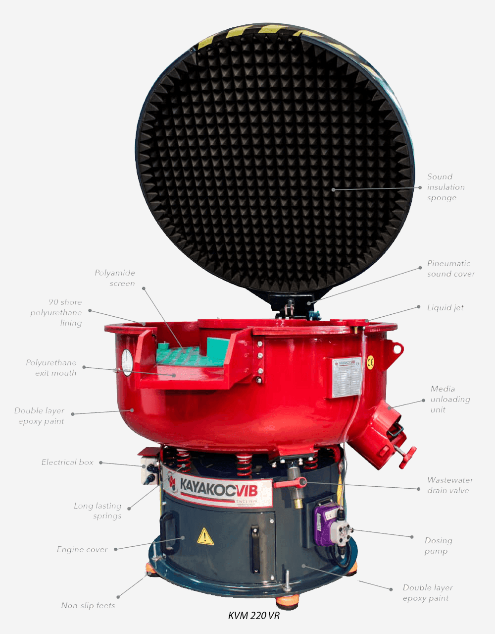
Circular vibratory finishing machines operate by imparting a toroidal flow to the media mass. Parts and media circulate together, with media sliding against part surfaces at low to moderate contact pressure. This makes circular vibratory machines well suited for CNC parts where dimensional stability is required alongside consistent deburring. The KAYAKOCVIB KVM series circular vibratory machines, for example, are commonly used for steel and aluminum CNC components in automotive, general machining, and industrial production environments where repeatable edge conditioning without aggressive stock removal is required.
Centrifugal disc finishing machines operate at significantly higher energy levels. The spinning disc accelerates media against parts with greater contact force, producing much faster cycle times. For small high-precision CNC parts where burrs are light and cycle efficiency is important, centrifugal disc machines such as the KSM series can be effective. However, the higher energy environment increases dimensional risk if media selection, load ratio, and cycle time are not carefully controlled. Centrifugal disc finishing is generally not recommended for parts with very tight tolerance features unless sample validation confirms acceptable dimensional change.
Trough vibratory finishing machines handle long or large CNC parts that cannot tumble freely in circular machines. For shaft components, long bores, or complex elongated profiles, a trough machine maintains more controlled part orientation and reduces collision damage risk. When deburring CNC tolerances on long shafts or rails, trough machines are often the safer choice mechanically.
Drag finishing machines provide the highest degree of process control. Parts are fixtured individually and drawn through a rotating media mass at controlled speed, depth, and angle. For precision CNC parts such as cutting tools, mold inserts, or implant components where dimensional change must be held to micron-level tolerances, drag finishing delivers repeatable, measurable material removal with minimal risk of part-to-part contact or uncontrolled exposure.
Process Parameter Reference for CNC Deburring
The table below summarizes key process parameters and their typical roles in controlling dimensional risk during CNC part deburring. Actual values must be validated through sample testing for each specific part and process configuration.
| Parameter | Effect on Dimensional Risk | Typical Control Action |
|---|---|---|
| Media abrasion grade | Higher abrasion increases material removal rate | Select lowest grade that removes the target burr |
| Media size and geometry | Larger media contacts broader surface areas | Use smaller media near tight tolerance features |
| Cycle time | Longer cycles increase total material removal | Minimize cycle time after burr removal is confirmed |
| Compound concentration | Higher concentration reduces cutting rate slightly | Fine-tune concentration to balance deburring and protection |
| Machine energy setting | Higher amplitude increases media pressure on parts | Use lowest amplitude that achieves consistent burr removal |
| Load ratio (parts to media) | Higher part load increases part-to-part contact risk | Maintain recommended media-to-part volume ratio |
Media Geometry and Feature Access
Media geometry affects which surfaces receive abrasive contact. Spherical media contacts all exposed surfaces relatively uniformly but has limited ability to reach into recessed areas. Triangular or wedge-shaped media can enter larger chamfers and cross-holes. Cylindrical media has directional contact properties. For CNC parts with both tight tolerance features and internal burrs requiring removal, media geometry selection must balance access to the burr location against exposure of the critical surface.
A common engineering decision point is whether to use a single media type that reaches all target surfaces or to accept that internal burrs may require a separate finishing pass or manual operation. Attempting to reach a deep internal burr with aggressive media that also contacts precision external surfaces often creates more dimensional risk than leaving the internal feature to a targeted manual deburring step.
Media size also governs lodging risk. If media is small enough to enter bores, slots, or pockets during finishing, it may become trapped inside the part. Lodged media causes downstream quality failures and represents a process control problem. For CNC parts with through-holes or internal channels, media size must be selected so that the smallest media piece cannot enter the smallest accessible feature. This is a manufacturing safety rule, not a finishing preference.
Protecting Specific Feature Types
Threaded features are particularly vulnerable during mass finishing. External threads can lose thread form if exposed to aggressive media contact for extended cycles. Internal threads are less exposed but can accumulate media or compound residue if not cleaned after finishing. The standard approach for external threads is to minimize cycle time to the shortest period that removes the target burr, and to validate thread gauge acceptance after finishing before committing to production volume.
Bore fits and bearing seats require surface condition control in addition to dimensional control. If the media cycle polishes the bore surface and changes the surface roughness significantly, the functional behavior of the fit may change even if the dimensional measurement remains within tolerance. This is relevant for interference fits and sealed bearing applications where surface texture contributes to functional performance.
Sealing faces and gasket surfaces must be treated carefully. These surfaces often require specific surface roughness targets, and deburring media that is too aggressive may create a rougher finish than the original machined surface. The goal in these cases is not only to remove the burr but to arrive at a controlled surface roughness that is compatible with the sealing requirement.
Process Validation Before Production Release
No deburring process for tolerance-critical CNC parts should be released to production volume without a structured validation sequence. The minimum validation steps for protecting deburring CNC tolerances are as follows.
- Define all tolerance-critical features on the part drawing and assign acceptable dimensional change limits for the finishing process.
- Measure the critical features on sample parts before finishing using calibrated instruments appropriate to the tolerance band.
- Run a timed finishing cycle at the proposed machine settings, media type, compound concentration, and load ratio.
- Measure the same critical features after finishing and calculate dimensional change per feature.
- Confirm that all features remain within the acceptable change limit.
- Inspect burr removal completeness and edge condition against the drawing requirement.
- If dimensional change exceeds limits, adjust media grade, cycle time, or compound concentration and repeat.
- Document the validated parameters as the production process specification.
This sequence applies to any change in part material, part geometry, media type or batch, compound type, or machine configuration. Process validation is not a one-time activity. It is the engineering foundation that separates controlled deburring from uncontrolled material removal.
Practical Considerations for Mixed Metal Production
Many CNC machining environments process steel, stainless steel, and aluminum parts through the same finishing equipment. Mixing aluminum and steel parts in the same finishing batch is generally not acceptable because the hardness difference means aluminum parts will receive disproportionately high material removal relative to steel parts under identical process conditions. Contamination is also a risk: steel particles embedded in aluminum surfaces can cause corrosion in service.
When running mixed metal CNC production, separate media sets and separate process programs for aluminum and steel batches are the standard industrial practice. This is not only a quality requirement but also a machine management requirement, since media that has processed steel parts carries steel contamination that can transfer to subsequent aluminum batches if not separated.
Frequently Asked Questions
How much material is typically removed during vibratory deburring of CNC parts?
Material removal during vibratory deburring depends on media abrasion grade, cycle time, compound concentration, and machine amplitude. For light deburring of steel CNC parts with fine-cut ceramic media, surface material removal is commonly in the range of a few micrometers per surface in a standard production cycle, but this must be validated for each part and process configuration. Tight tolerance features must be measured before and after processing to confirm that dimensional change is within acceptable limits.
Can vibratory finishing damage thread profiles on CNC parts?
Aggressive media, long cycle times, or high machine energy can wear external thread profiles. Standard practice is to use the minimum cycle time and lowest effective media abrasion grade for the target burr, and to verify thread gauge acceptance after the finishing cycle before full production release.
Is drag finishing necessary for all precision CNC parts?
Drag finishing is not necessary for all precision CNC parts. It is most relevant when dimensional change must be held to micron-level tolerances, when part-to-part contact in tumbling machines is not acceptable, or when the part geometry requires controlled single-part processing. For many standard CNC parts, a correctly configured vibratory machine with validated media and cycle time provides sufficient dimensional control.
Can aluminum and steel CNC parts be finished in the same batch?
Aluminum and steel CNC parts should not be finished in the same batch. The hardness difference creates unequal material removal, and steel particle contamination can embed in aluminum surfaces. Separate batches, separate media sets, and separate process programs are required for mixed metal production environments.
Related Process Equipment
Related Video Demonstration
Conclusion
Protecting deburring CNC tolerances requires engineering control at every stage of the process, from media selection and machine type to cycle time, compound concentration, and load ratio. There is no universal setting that works for all CNC parts. Each combination of part geometry, material, burr location, and tolerance requirement defines a specific process envelope that must be established through sample testing and dimensional validation. The practical engineering goal is to remove the burr with the lowest possible material removal rate on critical surfaces, confirmed by measurement before and after processing. Whether using a circular vibratory machine for production volume or a drag finishing unit for high-precision components, dimensional stability during deburring is a repeatable outcome when process parameters are controlled and validated systematically.
Sorry, the comment form is closed at this time.