



21 Jul Centrifugal Finishing Cycle Time
Centrifugal finishing cycle time is one of the most consequential process variables in high-speed mass finishing. Unlike conventional vibratory finishing, centrifugal disc machines generate significantly higher relative motion between media and parts, which compresses what would otherwise be a lengthy surface treatment into a much shorter production window. Understanding how cycle time is determined, what factors influence it, and how to optimize it for different part families is essential for production engineers who need consistent surface quality with minimal floor time.
In This Article
Why Cycle Time Behaves Differently in Centrifugal Disc Finishing
In vibratory finishing, abrasive action results from low-amplitude, high-frequency vibration that creates a slow rolling mass movement. Cycle times for deburring or surface smoothing in vibratory systems typically range from 20 minutes to several hours depending on the application. Centrifugal disc machines operate on a fundamentally different principle. A rotating disc at the base of a stationary bowl creates centrifugal force that drives the media and parts upward along the bowl wall and back down through the center in a continuous toroidal flow. This produces media-to-part contact intensity that is typically several times higher than in vibratory machines.
As a result, centrifugal finishing cycle time for comparable deburring or surface smoothing tasks can be significantly shorter. What may require 60 to 90 minutes in a vibratory machine may be achievable in 5 to 20 minutes on a centrifugal disc machine, depending on part geometry, material, burr condition, media type, and target surface quality. These figures are application-dependent and require validation through process sample testing before production release.
Part Material and Its Effect on Finishing Duration
Material hardness and surface sensitivity are primary drivers of how long the centrifugal disc process needs to run. Harder materials such as hardened steel or stainless steel require longer contact time to achieve the same edge rounding or surface smoothing compared to softer materials like aluminum or brass. Softer materials respond faster to abrasive media action but are also more susceptible to over-processing, which can lead to surface waviness, part deformation on thin sections, or excessive material removal from edges.
For aluminum and zamak parts, plastic media is generally the correct choice. Plastic media provides a lower cutting rate with controlled abrasion, which protects sensitive surfaces while still achieving burr removal and surface improvement. For steel and stainless steel parts, ceramic media is typically used because harder metals require stronger abrasive cutting action to remove burrs and condition surfaces within a practical cycle duration. Using plastic media on steel parts in a centrifugal disc machine would extend cycle time considerably and may not achieve the required deburring result.
Media and Compound Selection for Cycle Efficiency
Media geometry, size, and abrasive grade directly affect how much work is done per unit of processing time in centrifugal disc finishing. Smaller media enters into tighter geometries such as drilled holes, slots, and recessed pockets, but generates less force per contact event. Larger media carries more energy per contact but may not reach confined areas. Selecting the correct media size for the part geometry is essential not only for surface quality but for achieving the target centrifugal finishing cycle time without extending the run unnecessarily.
Abrasive compound also plays a significant role. For steel and iron parts, a deburring and polishing liquid compound formulated for ferrous metals is typically used alongside ceramic media. This combination maintains consistent cutting performance and prevents part staining during wet processing. For aluminum, zamak, or other non-ferrous metals, a compound matched to softer materials protects against surface discoloration and supports controlled material removal. The compound concentration in the process water affects both cutting efficiency and surface brightness, so correct dosing directly influences whether the target surface condition is reached within the planned cycle window.
Process Parameters That Control Finishing Duration
Several machine and process parameters interact to determine how quickly the centrifugal disc machine achieves the required result. These parameters should be understood as a system rather than as independent variables.
| Parameter | Effect on Cycle Time | Practical Consideration |
|---|---|---|
| Disc rotation speed | Higher speed increases media energy and reduces cycle time | Too high a speed can damage delicate parts or cause part-on-part collision |
| Media fill level | Correct fill level maintains toroidal flow and consistent contact | Under-filling reduces contact frequency; overfilling restricts part movement |
| Part-to-media ratio | Higher media ratio typically improves surface uniformity | Too many parts relative to media can reduce finishing consistency |
| Compound concentration | Correct dosing maintains cutting action throughout the cycle | Too low a concentration reduces abrasion; too high can cause foaming |
| Water flow rate | Continuous fresh compound supply sustains cutting efficiency | Excessive water flow dilutes compound and reduces abrasive performance |
| Media shape and grade | Higher-grade abrasive cuts faster and reduces cycle time | Aggressive media may require shorter cycle to prevent over-processing |
These parameters are interdependent. Increasing disc speed while using aggressive ceramic media and high compound concentration will produce a faster cycle but also a higher risk of part damage if the combination is not validated for the specific part geometry and material. Process development should systematically evaluate these variables and establish a validated parameter set before releasing the process to production.
Typical Cycle Time Ranges by Application
While exact cycle durations must be determined through process development and sample testing, general ranges based on common industrial applications provide a useful starting reference. For light deburring of CNC-machined aluminum components with small burrs and a moderate surface finish requirement, centrifugal disc finishing cycles may run as short as 5 to 10 minutes. For stainless steel fasteners requiring edge rounding and surface smoothing, cycles in the range of 10 to 20 minutes are common in many industrial applications. For surface polishing or pre-plate smoothing on precision parts, cycles may extend to 20 to 40 minutes depending on the starting Ra condition and the target specification.
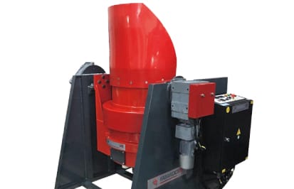
In medical device component finishing, where surface quality requirements are stringent and part geometries are often complex, process validation is essential before any cycle time can be declared acceptable. The same applies to aerospace precision components where dimensional tolerances and surface specifications are tightly controlled. For these applications, centrifugal disc machines such as the KAYAKOCVIB KSM series are used because they combine high finishing intensity with repeatable process control, but the specific cycle time must be confirmed through validated sample testing rather than assumed from reference data alone.
The Relationship Between Cycle Time and Surface Quality
Longer cycles do not automatically produce better surface quality. In centrifugal disc finishing, there is typically an optimal cycle duration beyond which additional processing provides diminishing returns or causes unwanted effects. If a part is processed beyond the point where the surface roughness plateau has been reached, continued abrasive action may begin rounding edges beyond the dimensional tolerance, removing more material than intended, or introducing a different surface texture as the media wears down. This is sometimes described as over-processing.
For production engineers, the correct approach is to establish the minimum effective cycle time that reliably achieves the required surface condition. This is determined by running a series of sample batches at progressively longer durations and measuring surface roughness, edge condition, and dimensional compliance at each stage. The result is a validated cycle envelope that defines the minimum and maximum acceptable processing time. Using this validated range in production prevents both under-processing and over-processing, which directly supports quality consistency and machine utilization efficiency.
Multi-Stage Cycles for Complex Surface Requirements
Some parts require sequential processing stages within the centrifugal disc machine to achieve a final surface condition that a single stage cannot produce efficiently. A common two-stage approach runs an initial cut-down stage using aggressive ceramic media to remove burrs and reduce surface roughness, followed by a second polishing stage using finer or less aggressive media to refine the surface to the target Ra. Running both operations in sequence on the same machine, with a media change between stages, can be more time-efficient than extending a single stage to attempt both outcomes simultaneously.
Multi-stage cycles are particularly common for parts destined for decorative finishing, electroplating, or hard coating, where the substrate surface must meet a specific pre-treatment condition. In these cases, centrifugal finishing cycle time is calculated as the sum of all stages, and the total cycle duration must fit within the production takt or batch processing window. If total cycle time across stages exceeds the available production window, the process may need to be divided across multiple machines or evaluated for an alternative approach such as drag finishing for the highest-quality polishing stage.
Automation and Cycle Time Repeatability
In automated finishing lines, consistent centrifugal finishing cycle time becomes a production planning requirement rather than just a process parameter. When the centrifugal disc machine is integrated into a production cell with automated loading, unloading, separation, washing, and drying, the cycle time directly determines line throughput and takt compliance. Any variation in cycle duration caused by inconsistent media loading, compound dilution drift, or operator intervention creates downstream timing problems across the integrated line.
Automated centrifugal disc systems that use programmable controllers with fixed cycle timers, automatic compound dosing, and consistent media replenishment routines substantially reduce cycle-to-cycle variation. For high-volume production in automotive fastener lines or CNC machined component finishing, this repeatability is as important as the cycle time value itself. The KAYAKOCVIB KSM series supports integration into automated finishing lines where consistent cycle execution, media management, and compound dosing contribute to stable production output across shifts.
Frequently Asked Questions
What is a typical centrifugal finishing cycle time for CNC aluminum parts?
For light deburring and surface smoothing of CNC-machined aluminum parts with small burrs, cycle times commonly range from 5 to 15 minutes using plastic media and appropriate compound. Actual duration depends on part geometry, burr size, media grade, disc speed, and target surface condition. Process validation through sample testing is required before production.
How does centrifugal disc finishing cycle time compare to vibratory finishing?
Centrifugal disc machines typically achieve comparable deburring and surface smoothing results in significantly less time than vibratory finishing. A vibratory process that requires 60 to 90 minutes may be achievable in 10 to 20 minutes on a centrifugal disc machine, depending on application conditions. The intensity difference is due to the centrifugal force generated by the rotating disc, which increases media-to-part contact energy substantially.
Can cycle time be reduced by increasing disc speed?
Increasing disc speed raises media energy and can reduce the time needed to achieve a given surface condition. However, excessive speed increases the risk of part-on-part collision, edge damage, and part deformation, particularly for delicate or thin-walled components. Speed adjustment must be evaluated alongside part geometry, media type, and acceptable process intensity before being applied in production.
How do I know if I am over-processing parts in a centrifugal disc machine?
Signs of over-processing include excessive edge rounding beyond dimensional tolerance, surface waviness on flat faces, unintended material removal on critical features, and part marking from impact. Establishing a validated maximum cycle time through sample testing and regular in-process dimensional and surface inspection is the standard method for detecting and preventing over-processing.
Related Machine and Process Resources
Related Video Demonstration
Conclusion
Centrifugal finishing cycle time is not a fixed value that can be selected from a chart. It is the result of a validated combination of machine settings, media selection, compound chemistry, part geometry, material properties, and target surface specification. For production engineers, the goal is to identify the minimum effective cycle time that reliably delivers the required surface quality within dimensional tolerances, then lock that parameter set into a controlled, repeatable process. Whether the application involves deburring CNC-machined steel components, surface smoothing aluminum die cast parts, or preparing precision medical components for further processing, the centrifugal disc finishing cycle must be developed and validated specifically for the part family before full production release. Machines such as the KAYAKOCVIB KSM series provide the process intensity and control architecture needed to support this validation, but the cycle time itself must always be confirmed through application-specific testing.
Sorry, the comment form is closed at this time.