



15 Jul Deburring Without Part Damage
Deburring without part damage is one of the most common process challenges in mass finishing operations across CNC machining, automotive, aerospace, fastener, and medical manufacturing environments. When parts arrive at the deburring stage with acceptable dimensional tolerance and surface condition, the finishing process must remove burrs and round edges without introducing new defects. In practice, part damage during deburring is often caused by incorrect media selection, overloaded machine chambers, insufficient compound dosing, or process parameters that are too aggressive for the part geometry or material. Understanding the root causes systematically is the most efficient path to eliminating the problem.
In This Article
Why Part Damage Occurs During Deburring
Part damage in vibratory deburring is rarely caused by a single factor. In most cases it results from a combination of variables acting together. The most frequent damage types include surface scratching, edge chipping, denting, part-on-part impingement, and media lodging in bores or recesses. Each of these has distinct root causes that must be diagnosed separately before any corrective action is applied.
Surface scratching typically indicates that the media abrasive grade is too aggressive for the base material, or that media-to-part contact is occurring at excessive velocity. Denting and edge chipping are more common in brittle materials such as hardened steel or thin-walled aluminum components and usually indicate that part-on-part collisions are occurring inside the machine bowl or trough. Media lodging in small holes or pockets is a geometry-related problem that requires media size selection to be re-evaluated against part features.
Root Cause Categories
A structured root cause review helps engineers identify the correct corrective action without changing multiple variables at once. The four primary root cause categories for part damage during deburring are media-related causes, machine loading and motion causes, compound and water causes, and part geometry or part-specific causes.
| Damage Type | Most Likely Root Cause | Corrective Direction |
|---|---|---|
| Surface scratching | Media too aggressive or worn media breakdown | Change media type or grade, increase compound dosing |
| Edge chipping | Part-on-part collision, excessive amplitude | Reduce load ratio, lower machine amplitude |
| Denting | Heavy part-on-part impingement at high intensity | Reduce load, use separation media or dividers |
| Media lodging | Media too large or too small for part geometry | Reselect media size relative to smallest bore |
| Staining or discoloration | Incorrect compound, insufficient rinsing, water contamination | Review compound selection and rinsing sequence |
Machine Loading and Motion-Related Causes
Machine overloading is one of the most common reasons part damage occurs even when media and compound selection appear correct. In circular vibratory finishing machines, the working mass inside the bowl must maintain a flowing, rotating motion for the finishing action to be uniform and controlled. When too many parts are loaded relative to media volume, parts begin to contact each other directly rather than being cushioned by media between them. This is the primary cause of part-on-part denting and edge chipping.
The recommended part-to-media load ratio varies depending on part size, geometry, and material, but in most vibratory finishing applications the parts should not exceed 10 to 30 percent of the total working volume by weight. Delicate or thin-walled parts often require a lower part ratio. This must be confirmed through sample testing because part geometry strongly influences the correct loading range.
Amplitude settings also directly affect impact energy inside the machine. Higher amplitude increases cutting action but also increases the collision energy between parts and between parts and media. For sensitive parts or parts with fine surface requirements, reducing amplitude and extending cycle time is usually more effective than running at maximum machine intensity. Frequency adjustments, where the machine allows it, offer additional control over media flow behavior.
Media Selection for Damage Prevention
Selecting the correct media type and geometry is central to achieving deburring without part damage. The media must be capable of removing the target burr while remaining gentle enough not to damage finished surfaces, fine edges, or dimensional features.
For steel and stainless steel parts, ceramic media is generally the correct starting point because the material hardness requires sufficient cutting action. Ceramic media comes in a wide range of shapes including triangle, cylinder, cone, and satellite geometries. The shape must be selected so that the media does not enter holes, slots, or recesses where it would become trapped. A common rule is that media size should be larger than the smallest opening on the part by a factor of at least 1.5 to 2 times.
For aluminum parts, plastic media is generally preferred because aluminum is softer and more sensitive to aggressive abrasive action. Plastic media provides a gentler cutting action and reduces the risk of surface scratching. If ceramic media is used on aluminum without sufficient compound lubrication, the result is almost always surface damage and a dull, scratched appearance instead of a clean deburred finish.
For mixed-metal batches, the media choice must be evaluated against the softest material in the batch. Running aluminum and steel parts together in the same batch is generally not recommended because the media selection for one material will be incorrect for the other, and part-on-part damage between different materials is difficult to control.
Compound and Water Management
Finishing compound serves multiple functions in wet vibratory deburring. It lubricates the media-to-part contact surface to reduce scratching, it suspends removed metal fines to prevent them from redepositing on part surfaces, it controls pH to protect base materials from oxidation, and it assists in cleaning the part surface during the finishing cycle.
Insufficient compound flow is a frequent cause of surface scratching and staining even when media type is correct. The compound must be dosed at a rate appropriate for the machine size, part material, and media type. For steel parts, a deburring and polishing liquid such as a 943-type compound is commonly used. For aluminum and zamak parts, an 085-type compound is more appropriate because it is formulated for non-ferrous metals. A 028-S degreasing liquid is typically used alongside the main compound to assist in removing oils and contamination from machined parts before or during the finishing cycle.
Water flow rate also affects finishing performance. Too little water causes the media and parts to run dry, which increases abrasive cut and surface damage risk significantly. Too much water dilutes the compound and reduces finishing effectiveness. In most continuous-flow wet vibratory systems, water and compound are metered separately and adjusted based on the foam level and condition of the slurry exiting the drain.
Process Parameters That Control Finishing Safety
Several process parameters must be set correctly together to achieve deburring without part damage consistently. Changing only one parameter at a time during troubleshooting helps identify which variable is causing the problem.
- Amplitude: Controls the intensity of media and part movement. Lower amplitude reduces collision energy for sensitive parts.
- Cycle time: Longer cycles at lower intensity are generally safer than short cycles at maximum intensity for delicate parts.
- Part load ratio: Must be kept within the range that prevents direct part-on-part contact.
- Compound dosing rate: Insufficient dosing leads to dry running and surface scratching.
- Water flow rate: Must maintain a clean, lubricated slurry without over-diluting the compound.
- Media size and shape: Must be selected to match part geometry, especially regarding hole and recess dimensions.
- Media fill level: The bowl or trough must be filled to the manufacturer-specified working level for correct mass motion.
Machine Selection Influence on Part Safety
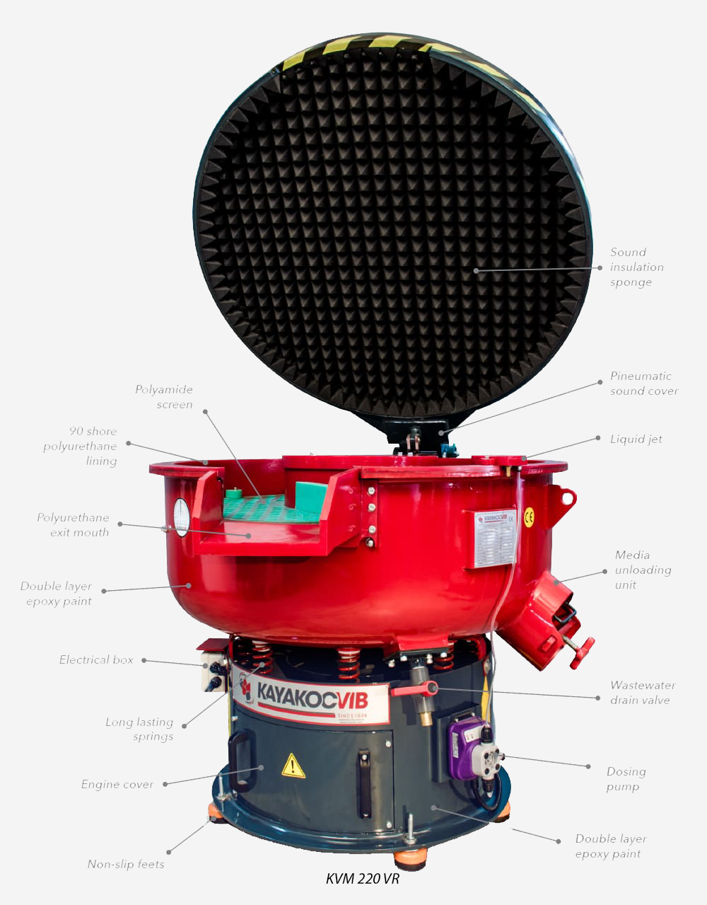
The machine type itself influences how safely different parts can be deburred. Circular vibratory finishing machines, such as the KAYAKOCVIB KVM series, are well suited for small to medium parts with compact or moderately complex geometries. The circular bowl geometry creates a smooth toroidal flow that moves parts gently through the media mass when the machine is loaded correctly. This makes them suitable for a wide range of CNC machined parts, fasteners, and general metal components where controlled deburring and edge rounding are required.
For long, slender, or asymmetric parts that may tumble end-over-end in a circular bowl and suffer edge damage, trough-type vibratory machines offer a more controlled linear flow that reduces the risk of uncontrolled part movement. The KAYAKOCVIB TVM series is designed for these geometries and allows long parts to remain oriented during the finishing cycle, which reduces the chance of edge chipping and impact damage.
For very small, high-precision, or thin-walled parts where even standard vibratory finishing introduces too much risk, centrifugal disc finishing or drag finishing machines can provide a more controlled and gentler finishing action with lower collision energy between parts.
Prevention Checklist Before Production Release
Before releasing a new deburring process into production, process engineers should validate the following points through sample testing. Skipping validation steps is a common reason damage problems emerge only after full production begins.
- Confirm media type and grade are appropriate for the base material.
- Confirm media geometry does not enter any holes, slots, or recesses on the part.
- Set part-to-media load ratio at the lower end of the recommended range for the first test.
- Confirm machine amplitude is appropriate for part weight and wall thickness.
- Confirm compound type is correct for the base material and dosing rate is within recommended range.
- Confirm water flow rate maintains a clean slurry without dry running.
- Run a small batch of sample parts for the full planned cycle time and inspect for all damage types before approving the process.
- Document the validated parameters as the production baseline.
Frequently Asked Questions
What is the most common cause of part damage during deburring?
In most industrial applications, part-on-part collision caused by overloading the machine chamber is the most frequent cause of denting and edge chipping. Incorrect media selection is the most common cause of surface scratching.
Can aluminum and steel parts be deburred together in the same batch?
This is generally not recommended. The media and compound requirements for aluminum differ significantly from steel, and parts of different materials contacting each other can cause surface damage. Separate batches with material-appropriate media and compound selections are strongly preferred.
How do I know if media is lodging inside part features?
Inspect parts immediately after unloading. If media pieces are found inside holes, slots, or recesses, the media size is too small relative to those features. Select a larger media size so that the smallest piece cannot enter the smallest opening on the part.
Does longer cycle time always cause more damage?
Not necessarily. If process intensity is low and the correct media and compound are in use, longer cycle times may be safer than short high-intensity cycles for delicate parts. However, excessive cycle time with aggressive media can cause over-finishing, rounding of features, or dimensional loss. Cycle time must be validated for each part and process combination.
Related Process Equipment
Related Video Demonstration
Conclusion
Achieving consistent deburring without part damage requires a systematic approach rather than trial-and-error media changes alone. The root causes span machine loading, media geometry and grade, compound dosing, water management, and amplitude settings, and they frequently interact with each other. Addressing each variable category in sequence, validating with sample parts before full production, and documenting the confirmed process baseline are the engineering steps that reliably eliminate damage problems. For parts with unusual geometry, very thin walls, or tight surface tolerances, machine type selection also plays a significant role, and circular vibratory, trough vibratory, or alternative finishing technologies should each be evaluated against the specific part requirements before a production process is committed.
Sorry, the comment form is closed at this time.