



14 Jul Deburring Quality Control
Deburring quality control is the systematic process of verifying that burrs, sharp edges, and surface defects have been consistently removed from machined or formed parts before they proceed to the next production stage. Across industries such as CNC machining, automotive, aerospace, medical, and fastener manufacturing, inadequate deburring control leads to assembly failures, tool damage, coating adhesion problems, and safety hazards. Establishing a structured quality control framework specific to the deburring process reduces scrap rates, supports process repeatability, and ensures that surface finishing outputs meet engineering specifications.
In This Article
What Deburring Quality Control Covers
Deburring quality control spans more than a visual check at the end of a finishing cycle. It includes pre-process inspection of incoming parts, validation of machine settings and media condition, in-process monitoring, and post-process surface verification. Each stage of control serves a distinct engineering function. Pre-process inspection identifies burr severity and surface condition before finishing begins. In-process monitoring ensures that machine parameters remain within validated ranges. Post-process inspection confirms that edge condition, surface roughness, and part geometry meet the drawing or functional specification.
The scope of quality control also depends on the part application. A structural bracket in automotive manufacturing may require edge rounding within a defined radius tolerance. A medical implant component may require a surface finish within a specific Ra range and the complete absence of loose particles. A precision aerospace fitting may require dimensional verification after edge treatment to confirm that no material was removed from functional surfaces. The quality control checklist must reflect the specific engineering requirement for each part family.
Typical Parts, Materials, and Defect Profiles
Industrial deburring applications involve a wide range of materials and part geometries. Steel and stainless steel components from CNC turning, milling, or grinding operations typically exhibit tight burrs along tool paths, cross-hole intersections, and thread entries. Aluminum die castings and machined aluminum parts may have thinner but more fragile burrs at parting lines, drilled holes, and milled edges. Stamped steel parts often carry rollover burrs along punched edges. Fasteners carry thread burrs and head-to-shank transition burrs. Each defect profile requires a different level of finishing intensity to achieve consistent results without over-processing.
Material sensitivity is a key factor in deburring quality control. Aluminum and softer alloys are more susceptible to surface scratching from aggressive ceramic media. Steel and stainless steel can tolerate higher process intensity but may require specific media geometry to address internal features such as blind holes or narrow slots. Mixed material batches should generally be avoided in mass finishing because different materials respond differently to the same process settings, making consistent deburring quality control more difficult to achieve.
Deburring Quality Control Checklist
The following checklist organizes the key inspection and validation points across the full deburring process sequence. It is intended as a practical engineering reference for process engineers, quality managers, and production supervisors.
Pre-Process Inspection
- Confirm part material, alloy grade, and hardness match the validated process specification.
- Inspect incoming parts for burr size, location, and severity to confirm that the scheduled process can address the defect profile.
- Verify that parts are free from heavy contamination such as cutting oil, chips, or coolant deposits that could affect media and compound performance.
- Confirm that part geometry does not create media lodging risk in blind holes, narrow slots, or internal cavities.
- Check that sensitive surfaces, threads, or tight-tolerance bores are identified and protected if required by the process specification.
Machine and Media Setup Validation
- Verify that the correct machine type has been selected for the part geometry and batch volume.
- Confirm media type, shape, size, and condition. Replace worn or broken media before starting a production batch.
- Check media fill level in the machine bowl or trough. Under-filled or over-filled machines produce inconsistent results.
- Confirm compound type, concentration, and flow rate match the validated process specification for the material.
- Verify water flow rate and pressure if wet processing is used.
- Set machine amplitude, frequency, and process time according to the validated parameter sheet.
- Confirm that the separator is correctly set for part-media separation to prevent part damage or media carry-over.
In-Process Monitoring
- Check machine vibration level and bowl motion at the start of each production shift.
- Monitor compound foam level and adjust compound concentration if excessive or insufficient foam is observed.
- Inspect sample parts at intermediate cycle points for long finishing cycles to verify that the process is progressing as expected.
- Confirm media condition periodically during the shift. Heavily worn or contaminated media requires replacement.
- Verify that process water or compound pH is within the specified operating range.
Post-Process Inspection
- Inspect finished parts for complete burr removal at all specified edge locations.
- Verify edge rounding radius using a contact or optical measurement method if a dimensional tolerance has been specified.
- Check surface roughness Ra on representative surfaces if a surface finish specification applies.
- Confirm that no media pieces are lodged inside holes, slots, or recesses.
- Inspect for corrosion staining, discoloration, or surface smearing, especially on aluminum and stainless steel parts.
- Verify part cleanliness after washing and drying if integrated washing is part of the process line.
- Record inspection results on the process control sheet and compare against the validated acceptance criteria.
Machine Selection and Its Impact on Process Control
Machine selection directly determines how consistently deburring quality control targets can be achieved. Different machine types produce different finishing intensities, part-to-media contact patterns, and cycle time ranges. Selecting the correct machine for the application reduces variability and simplifies the quality control process.
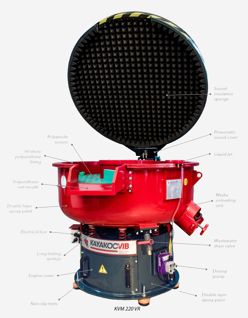
Circular vibratory finishing machines such as the KAYAKOCVIB KVM series are well suited for small to medium parts including CNC turned and milled components, fasteners, stamped parts, and general industrial parts. The circular bowl geometry creates uniform part-media contact and is effective for batch processing. These machines handle a wide range of media types and are suitable for wet deburring, edge rounding, and surface refinement.
Trough vibratory finishing machines are preferred for longer parts or delicate components that could be damaged by the rotational motion of a circular bowl. Centrifugal disc finishing machines such as the KAYAKOCVIB KSM series generate significantly higher finishing intensity than vibratory machines and are used for small precision parts with short cycle time requirements or high surface quality targets. Drag finishing machines are reserved for high-value parts such as cutting tools, precision implants, or mold components where controlled single-part processing is required.
| Machine Type | Typical Application | Process Intensity | Cycle Time Range |
|---|---|---|---|
| Circular Vibratory (KVM) | CNC parts, fasteners, stamped parts | Medium | 30 to 120 minutes typical |
| Trough Vibratory (TVM) | Long or delicate parts | Medium | 30 to 120 minutes typical |
| Centrifugal Disc (KSM) | Small precision parts, high surface quality | High | 5 to 30 minutes typical |
| Drag Finishing (DRG) | High-value precision parts, implants, tools | Very High | 10 to 60 minutes typical |
Actual cycle times depend on part material, burr size, media type, and the surface quality target. These values represent typical industrial ranges and require validation through sample testing before production release.
Media and Compound Selection for Consistent Results
Media and compound selection is one of the most significant variables affecting deburring quality control outcomes. Incorrect media selection leads to incomplete burr removal, excessive material removal on functional surfaces, or surface damage that creates a new quality problem.
For steel and stainless steel parts, ceramic media is generally preferred because the harder cutting action matches the material hardness and produces effective burr removal. Ceramic media is available in a wide range of shapes including triangles, cylinders, cones, and stars, each suited to different part geometries. For aluminum, zamak, and softer alloys, plastic media is typically the correct choice to avoid aggressive surface scratching or dimensional loss on precision surfaces.
Compound selection must match both the material and the finishing objective. For steel parts, a deburring and polishing compound such as a 943-type liquid combined with a degreasing compound controls surface oxidation and supports consistent cutting. For aluminum parts, an 085-type compound is commonly used. For copper, brass, and yellow metals, a more acidic compound such as a 028-type liquid is appropriate. Compound concentration and flow rate must be validated and maintained within the specified range throughout the production run to ensure consistent deburring quality control from batch to batch.
Process Parameters That Control Edge Quality
Several process parameters directly affect the edge condition and surface quality of deburred parts. These parameters must be documented in a process specification sheet and checked at each production startup.
Machine amplitude and vibration frequency determine how aggressively the media acts on the parts. Higher amplitude increases cutting rate but may cause part-to-part contact damage with soft or thin-walled components. Process time is directly related to burr removal depth and edge rounding radius. Over-processing removes too much material from edges and may introduce dimensional change. Under-processing leaves residual burrs that do not meet the drawing specification.
Media-to-part ratio affects both process intensity and the risk of part damage from direct metal-to-metal contact. In most industrial applications, a media fill level of approximately 80 to 90 percent of the active bowl volume is maintained, with parts loaded according to the validated loading weight for the machine size. Actual loading parameters depend on part geometry, weight, and the specific machine configuration and must be confirmed through process trials.
Quality Control for Integrated Washing and Drying
When deburring is performed as a wet process, washing and drying after the finishing cycle are part of the complete quality control sequence. Residual compound, media fines, and metal particles must be fully removed before the part proceeds to coating, heat treatment, or assembly. Parts with compound or particle contamination on the surface can cause coating adhesion failures or assembly interference.
Industrial washing systems, including pressure washing and ultrasonic cleaning units, are used in finishing lines where part cleanliness is a defined specification. After washing, parts must be dried completely to prevent corrosion, particularly on steel and iron components. Drying systems such as circular vibratory dryers or trough dryers use warm air and corncob or walnut shell drying media to remove surface moisture without leaving residue. The drying stage should also be included in the post-process quality control inspection.
Troubleshooting Inconsistent Deburring Results
When finished parts fail the deburring quality control inspection, the root cause should be traced systematically before adjusting process parameters. Common causes of inconsistent results include worn or undersized media that no longer has sufficient cutting ability, incorrect compound concentration resulting in poor lubrication or insufficient surface activation, media lodging in part features that prevents adequate contact in recessed areas, and excessive part loading that reduces media-to-part contact ratio.
Process drift between shifts is a frequent source of quality variation in mass finishing. Media wear is gradual and reduces cutting rate over time. A media top-up schedule or replacement interval should be defined in the process control document. Compound concentration should be measured and adjusted at the start of each shift. Machine amplitude should be checked using a calibration reference point at regular intervals. Documenting these checks as part of the daily deburring quality control routine prevents gradual process drift from becoming a scrap or rework problem.
Frequently Asked Questions
How do you measure edge rounding after deburring?
Edge rounding radius can be measured using optical comparators, contact profilometers with edge measurement software, or calibrated radius gauges depending on the tolerance requirement. For general industrial applications, a visual reference standard with defined acceptable and reject samples is commonly used at the inspection station.
What causes burrs to remain after a vibratory finishing cycle?
Residual burrs after vibratory finishing typically result from worn media with insufficient cutting ability, incorrect media geometry that cannot reach the burr location, under-specified process time, or machine amplitude that is too low for the burr size. Media lodging in part features can also prevent contact at specific burr locations.
Can different materials be mixed in the same deburring batch?
Mixing aluminum and steel parts in the same batch is generally not recommended. Different materials respond differently to the same process settings, and metal-to-metal contact between harder steel and softer aluminum parts can cause surface damage. Separate process specifications should be maintained for each material group.
How often should finishing media be replaced?
Media replacement frequency depends on media type, process intensity, batch volume, and part material. A typical industrial practice is to top up media monthly and perform a full media inspection quarterly, replacing broken or undersized pieces. The actual interval must be determined through process monitoring and validated by surface quality results.
Related Process Equipment
Related Video Demonstration
Conclusion
Effective deburring quality control requires a structured approach that covers the full process sequence from incoming part inspection through machine setup, in-process monitoring, and post-process surface verification. The checklist framework presented here provides a practical reference for process engineers and quality managers who need to establish or audit a deburring control system. Consistent results depend on selecting the correct machine type for the application, maintaining validated media and compound specifications, and documenting process parameters for every production batch. Process capability must always be confirmed through sample testing and incremental production trials rather than assumed from machine specifications alone. A well-managed deburring quality control system reduces rework, supports downstream process reliability, and provides a defensible audit record for regulated industries.
Sorry, the comment form is closed at this time.