

05 Jul Vibratory Finishing Machine Capacity Calculation
Vibratory finishing machine capacity calculation is the engineering step that determines whether a selected machine can handle a given part volume, media load, and production schedule. Getting this calculation right before machine procurement prevents underloading, overloading, process inconsistency, and unnecessary capital expenditure. This article walks through the full calculation sequence, from defining working volume to estimating throughput, with practical guidance for CNC machined parts, automotive components, fasteners, and similar industrial applications.
In This Article
What Vibratory Finishing Machine Capacity Actually Means
Machine capacity in vibratory finishing refers to the gross working volume of the finishing bowl or trough, measured in liters. This is the total internal volume available for the combined load of parts and finishing media. It is not the volume of parts alone, and it is not the volume of media alone. The capacity figure printed on a machine specification sheet represents the maximum combined load volume the machine can process while maintaining effective vibratory motion and adequate part-to-media contact.
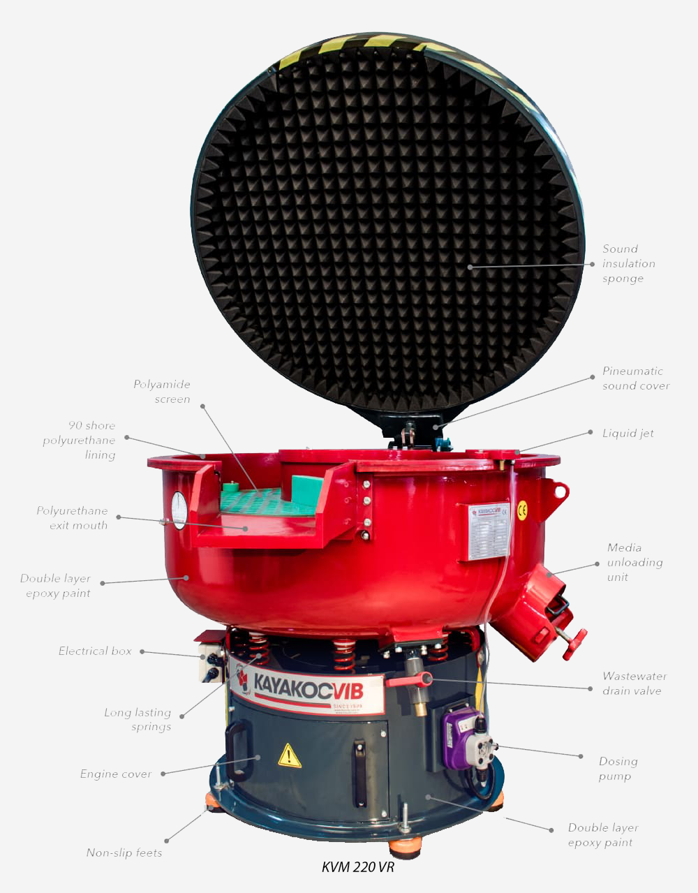
Two machine geometries are relevant here. Circular vibratory machines, such as the KAYAKOCVIB KVM series, have a toroidal bowl where parts and media travel in a helical circulation path. Trough vibratory machines, such as the KAYAKOCVIB TVM series, have an elongated channel that suits long or large parts that would orient poorly in a circular bowl. The capacity calculation method applies to both geometries, but loading ratios and part orientation constraints differ between them.
Core Variables in the Capacity Calculation
Before selecting a machine size, the following variables must be defined with reasonable accuracy. Each variable directly affects the calculation output.
- Part envelope volume: the approximate swept volume of one part, including its longest dimension in each axis
- Batch quantity: the number of parts to be processed per cycle
- Fill ratio: the proportion of the machine working volume that should be occupied by the combined part and media load, typically 80 to 90 percent of working volume
- Media-to-part ratio: the volumetric ratio of media to parts, which depends on part geometry, material, burr size, and required surface action
- Cycle time: the target finishing time per batch, which affects throughput calculation
- Shift hours and production volume: total daily or weekly part requirement
Each of these inputs must be established before the machine working volume can be calculated. Estimating any of them loosely will produce an unreliable capacity result.
Step-by-Step Capacity Calculation Process
The following sequence covers the standard engineering approach to vibratory finishing machine capacity calculation from part data to machine size selection.
- Calculate the bulk part volume per batch. Estimate the individual part envelope volume in liters. For irregular geometries, use the bounding box volume and apply a packing factor of 0.5 to 0.65 depending on part shape. Multiply by the number of parts per batch. This gives the total part volume in liters.
- Define the media-to-part volume ratio. For most CNC machined steel or stainless steel parts with moderate burrs, a media-to-part ratio of 3:1 to 5:1 is typical. For delicate aluminum parts or thin-walled components, a higher ratio such as 5:1 to 8:1 distributes the load more gently and reduces part-on-part contact. For heavy castings or parts with large burrs, a lower ratio may be acceptable if cycle time is extended. This ratio is application-dependent and should be confirmed through sample testing.
- Calculate total load volume. Add the part volume and the media volume. For example, if the part volume per batch is 20 liters and the media-to-part ratio is 4:1, the media volume is 80 liters. Total load volume is 100 liters.
- Apply the fill factor to determine required machine working volume. Divide the total load volume by the target fill ratio. Using a fill ratio of 0.85, a 100-liter total load requires a machine with a working volume of at least 118 liters. Rounding up to the next available machine size provides a safety margin and allows for batch volume variation.
- Verify throughput against production requirements. Divide the required daily part volume by the batch quantity to determine the number of cycles required per day. Multiply by the cycle time including loading, finishing, separation, and reloading time. Compare this to available shift hours. If the cycle count exceeds available time, either increase machine size, run parallel machines, or reduce cycle time through process parameter adjustment.
Fill Ratio and Why It Matters
Running a vibratory finishing machine at its full rated capacity is not always the correct operating point. Most circular vibratory machines are designed to operate most efficiently at 75 to 90 percent of their rated working volume. Underfilling reduces part-to-media contact frequency and slows the process. Overfilling suppresses the vibratory motion, reduces media circulation, and can cause part-on-part impingement damage or inconsistent deburring results.
For trough vibratory machines, fill level also affects how parts travel along the trough length. Underfilling a trough can allow heavy parts to sink to the bottom and receive less media action on complex surfaces. Overfilling reduces the spiral advance of parts toward the discharge end, which may cause batch mixing or uneven cycle time distribution along the trough length.
In practice, most process engineers target a fill ratio of 80 to 85 percent as a starting point and adjust based on observed circulation quality during sample trials.
Media Selection and Its Effect on Load Calculation
Media selection affects not only surface finish quality but also the effective density of the media load, which influences total load weight and machine drive requirement. Ceramic media is denser than plastic media, which means that a 3:1 media-to-part ratio with ceramic media places a much heavier load on the machine than the same ratio with plastic media. The working volume calculation remains the same, but the machine must be rated for the corresponding dynamic load in kilograms.
For steel and stainless steel parts, ceramic media with 943 deburring and polishing liquid is the typical starting point for moderate to heavy deburring. For aluminum parts, plastic media combined with 085 deburring and polishing liquid is generally preferred to avoid aggressive surface cutting and to protect softer base material. When degreasing is required in addition to deburring, 028-S degreasing liquid is commonly added to the compound circuit.
Media size and shape must also suit the part geometry. Undercut channels, blind holes, or recessed pockets that are smaller than the media piece size will not receive media action and will remain unfinished. This is a geometric constraint, not a capacity issue, but it must be identified during the capacity planning stage to avoid process gaps.
Throughput Calculation and Machine Sizing Logic
Once the single-batch machine volume is confirmed, throughput capacity across a full shift must be calculated to verify that one machine is sufficient or whether additional machines or parallel finishing lines are needed.
| Parameter | Example Value | Notes |
|---|---|---|
| Parts per batch | 500 | Based on part size and machine load |
| Cycle time per batch | 45 min | Including finishing, separation, and reload |
| Available shift hours | 8 hours (480 min) | Single shift operation |
| Cycles per shift | 10 | 480 min / 45 min per cycle |
| Parts per shift | 5,000 | 10 cycles x 500 parts |
| Required daily output | 8,000 parts | Production schedule requirement |
| Machines required | 2 | 8,000 / 5,000 rounded up |
This type of throughput table should be prepared during the machine selection phase. The numbers above are illustrative. Actual values depend on part size, media-to-part ratio, required surface quality, and cycle time confirmed through sample testing. Cycle time estimates before sample testing are approximations and should not be used as guaranteed production commitments.
Long Parts and Trough Machine Sizing
For parts whose longest dimension exceeds the practical diameter of a circular bowl, trough vibratory machines are the appropriate machine type. The working volume calculation follows the same logic, but the constraint is part length relative to trough width and depth rather than bowl diameter. A part that is 600 mm long, for example, requires a trough whose internal width and depth allow the part to tumble or slide without bridging across the trough walls.
When sizing a trough machine, the engineer must verify both the volumetric capacity for the media and part load, and the geometric clearance for the longest part dimension. Trough machines can also be configured for continuous or semi-continuous operation, where parts are fed at one end and discharged at the other through a flap gate or overflow system. In this configuration, throughput calculation changes from a batch model to a flow rate model, and the media fill level must be maintained continuously.
Machine Capacity and Process Parameter Interaction
Vibratory finishing machine capacity is not an isolated number. It interacts directly with vibration amplitude, vibration frequency, media fill level, compound flow rate, and water flow rate. Changing any of these parameters without recalculating the load balance can reduce process effectiveness even if the volumetric capacity is correctly sized.
Amplitude and frequency together control the intensity of the finishing action. Higher amplitude at a constant frequency increases media aggressiveness and can reduce cycle time, but it also increases stress on the machine structure and may not be suitable for delicate parts. Lower amplitude with higher frequency produces finer, gentler finishing action, which is appropriate for precision parts where dimensional change must be minimized.
Compound flow rate must be matched to the batch volume. Insufficient compound causes dry spots in the media mass, uneven surface conditioning, and potential part staining. Excessive compound dilutes the finishing chemistry and increases wastewater volume without proportional process benefit. A typical starting point for compound flow rate is 0.5 to 2.0 liters per hour per 100 liters of machine working volume, but this must be adjusted based on compound concentration, media absorption, and observed surface quality.
Capacity Calculation for Mixed-Part Production
In facilities where multiple part types share the same finishing machine, the capacity calculation must account for the most demanding part type in each run. Running aluminum and steel parts in the same batch is generally not recommended because their hardness differences cause uneven media wear and may damage softer parts. When mixed-metal batches are unavoidable, media selection and compound must be evaluated for compatibility with all materials in the batch, and the fill ratio must be based on the heaviest or most geometrically complex part type.
For facilities processing a wide range of part families, a capacity matrix listing each part type, its batch volume, media ratio, and cycle time is a practical planning tool. This matrix helps identify bottlenecks, schedule finishing windows, and determine when a second machine is justified by production volume rather than guesswork.
Frequently Asked Questions
How do I estimate part volume for irregular CNC machined parts?
Use the bounding box volume of the part and apply a packing factor between 0.5 and 0.65 depending on how compactly the parts nest together. For solid, blocky parts, use a higher packing factor. For parts with large open areas or complex profiles, use a lower factor. Sample loading trials are the most accurate method when part geometry makes estimation unreliable.
What media-to-part ratio should I use as a starting point?
A ratio of 3:1 to 5:1 by volume is a common starting range for most industrial deburring applications. Higher ratios up to 8:1 are used for delicate or thin-walled parts to reduce part-on-part contact. The exact ratio must be confirmed through sample finishing trials before production commitment.
Can I run a vibratory machine at 100 percent fill capacity?
Operating at exactly 100 percent of rated working volume is not recommended. Most machines perform best at 80 to 90 percent fill. Running at full rated volume leaves no margin for batch size variation and can reduce media circulation quality, particularly in circular bowl machines.
How does cycle time affect machine capacity planning?
Cycle time directly determines how many batches a machine can complete per shift. Longer cycle times reduce throughput even if the machine is correctly sized for single-batch volume. If throughput is insufficient, cycle time reduction through parameter optimization or machine size increase are both viable paths, depending on whether the root cause is process chemistry or mechanical capacity.
Related Machine and Process Resources
Related Video Demonstration
Conclusion
Accurate vibratory finishing machine capacity calculation requires more than reading a machine volume specification. It requires defining batch part volume, selecting an appropriate media-to-part ratio, applying a realistic fill factor, and then verifying that the resulting throughput matches the production schedule. Each of these steps depends on part geometry, material, required surface quality, and cycle time, all of which must be confirmed through sample trials before final machine selection. For standard CNC machined, automotive, fastener, or aerospace component finishing applications, following the structured calculation sequence described here provides a reliable engineering basis for machine sizing decisions. Whether the application calls for a circular machine such as the KVM series for compact batch parts or a trough machine for longer components, the capacity calculation logic remains the same and should always be validated against real production data before committing to a machine investment.
Sorry, the comment form is closed at this time.