
04 Jul CNC Deburring Case Study
This CNC deburring case study documents how a mid-size CNC machining supplier transitioned from manual bench deburring to a fully automated vibratory finishing line. The supplier produced steel, stainless steel, and aluminum components for automotive and general industrial customers, with batch sizes ranging from 200 to 2,000 parts per run. Rising labor costs, inconsistent edge quality, and increasing customer rejections for burr and surface defects created pressure to evaluate an automated alternative.
In This Article
Production Context and the Problem with Manual Deburring
The facility operated twelve CNC turning and milling centers. After machining, parts moved to a manual deburring station staffed by three operators working with hand files, abrasive brushes, and bench-mounted rotary tools. The station handled mixed part families across steel, stainless steel, and aluminum in the same shift.
Several problems had accumulated over time. Edge consistency varied between operators and between shifts. Thin aluminum parts occasionally showed surface scratches from aggressive manual work. Cycle time per batch was difficult to predict. Quality audit records showed that burr-related rejections averaged around 4 to 6 percent across a twelve-month period, with the highest rejection rates on stainless steel prismatic parts with internal pockets.
The engineering team defined three primary requirements for an automated solution: consistent edge rounding to a controlled profile, surface roughness improvement or at minimum no degradation from pre-finishing condition, and a cycle time per batch that allowed the finishing station to keep pace with machining output without creating a bottleneck.
Process Assessment Before Machine Selection
Before selecting equipment, the process team conducted a structured assessment of the part families being processed. This step is often skipped in cost-driven automation projects, but it directly affects machine type, media selection, and compound chemistry.
The assessment covered four variables for each part family: base material, part geometry and weight, burr condition after machining, and required surface finish after deburring. Results showed three distinct groups. The first group consisted of small aluminum turned parts with light burrs and smooth surface requirements. The second group included medium-size steel milled housings with moderate burrs on edges and chamfers. The third group covered stainless steel prismatic parts with internal pockets and cross-holes, which had the most problematic burr condition and the tightest inspection criteria.
This segmentation directly influenced the recommendation to use two machine types rather than a single universal installation. Forcing all three part families through identical process conditions would have required compromises that either damaged aluminum parts or left burrs on stainless steel components.
Machine Selection and Process Route Design
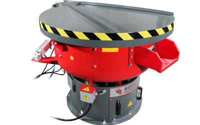
For aluminum turned parts and steel housings, the team specified circular vibratory finishing machines. A circular vibratory machine such as the KAYAKOCVIB KVM series provides continuous toroidal mass movement suitable for batch processing of mixed small to medium parts. The circular bowl geometry allows consistent media-to-part contact across the full batch without requiring manual repositioning. This machine type is well established for CNC turned and milled parts in steel, stainless steel, and aluminum where moderate edge rounding and surface improvement are the primary targets.
For the stainless steel prismatic parts with internal features, a centrifugal disc finishing machine was recommended. The KSM centrifugal disc series generates higher finishing intensity than standard vibratory machines, which is relevant when stainless steel burrs require more mechanical energy to remove without unacceptably long cycle times. The higher G-force environment in centrifugal disc finishing also improves compound penetration into pockets and cross-holes.
The process route for each part family was defined as a complete sequence: loading, wet finishing, part-media separation, rinsing, and drying. Separation was handled by integrated vibrating screen separators matched to the media size used in each machine. Rinsing was incorporated after separation to remove compound residue before drying. Drying used a corncob-based drying media system for steel parts, while aluminum parts were air-dried with low residual moisture.
Media and Compound Selection by Material Group
Media and compound selection followed material-specific logic. Mixing ceramic and plastic media in the same machine was avoided because the two materials have different cutting rates and densities, which creates unpredictable results and complicates process control.
For aluminum turned parts, plastic media was specified. Plastic media is less aggressive than ceramic, which protects the softer aluminum surface while still providing sufficient cutting action to remove light machining burrs. The finishing compound used was a deburring and polishing liquid formulated for non-ferrous metals, which supports cutting without staining or chemical attack on the aluminum surface. Degreasing liquid was included in the rinse stage to remove machining oil and coolant residue carried into the finishing bowl.
For steel housings, ceramic media was selected. Ceramic media provides the mechanical cutting force needed to remove harder steel burrs efficiently. A deburring and polishing compound suitable for ferrous metals was paired with the ceramic media to support consistent stock removal and surface improvement. The same degreasing liquid used for aluminum was applied in the rinse stage.
For stainless steel prismatic parts in the centrifugal disc machine, a fine-cut ceramic media with a geometry matched to the smallest internal pocket dimension was used. Undersized media creates lodging risk in internal features, so media shape and size must be validated before production release. Compound selection for stainless steel followed the same ferrous chemistry logic as the steel parts.
Step-by-Step Process Sequence After Automation
- Parts unloaded from CNC machines are collected in part-specific carriers or bins. Parts from different material groups are kept separate throughout the finishing line.
- Parts are loaded into the appropriate machine: KVM circular vibratory machine for aluminum and steel families, KSM centrifugal disc machine for stainless steel prismatic parts.
- Finishing media is pre-loaded into the machine bowl at the validated fill level. Compound and water are metered in through an automatic dosing unit connected to the machine.
- The finishing cycle runs at the validated amplitude and frequency settings for the material group. Cycle time is controlled by a timer with process parameters stored in the machine controller for each part program.
- At cycle end, the separation gate opens and the part-media mix discharges onto the vibrating screen separator. Media passes through the screen and returns to the machine bowl or a holding hopper. Parts are retained on the screen and conveyed forward.
- Parts pass through a rinse station where clean water and degreasing compound are applied to remove finishing compound residue and loose abrasive particles.
- Parts enter the drying stage. Steel and stainless steel parts use a heated drying system. Aluminum parts are handled through ambient air drying or a low-temperature drying conveyor depending on part geometry and surface sensitivity.
- Dried parts move to a visual inspection station where edge condition, surface finish, and cleanliness are checked against reference samples before release to the next production stage.
Process Parameters and Adjustment Logic
Setting the correct process parameters is essential for consistent results in an automated finishing line. The key variables for circular vibratory machines are amplitude, frequency, media fill level, compound concentration, water flow rate, and cycle time. For centrifugal disc machines, the disc rotation speed, compound dosing rate, and cycle time are the primary control parameters.
| Parameter | Aluminum Turned Parts | Steel Housings | Stainless Steel Prismatic Parts |
|---|---|---|---|
| Machine Type | KVM Circular Vibratory | KVM Circular Vibratory | KSM Centrifugal Disc |
| Media Type | Plastic | Ceramic | Fine Ceramic |
| Cycle Time | Typically 30 to 60 minutes | Typically 45 to 90 minutes | Typically 10 to 25 minutes |
| Compound | Non-ferrous deburring liquid | Ferrous deburring liquid | Ferrous deburring liquid |
| Separation | Vibrating screen | Vibrating screen | Vibrating screen |
Cycle times shown above are indicative and depend on burr size, part geometry, media condition, and compound concentration. All cycle times require validation through sample runs before production release. Media wear over time reduces cutting efficiency, so periodic media top-up and replacement schedules must be part of the production maintenance plan.
Validation Before Production Release
Before releasing the automated process to full production, a structured validation sequence was completed for each part family. This step is necessary regardless of how well the process is theoretically designed, because actual results depend on part-specific geometry, burr distribution, and material batch variation.
Validation included three sample runs per part family at the defined process parameters. After each run, parts were inspected for edge condition against a pre-defined acceptance gauge or visual reference standard. Surface roughness was measured with a contact profilometer at defined measurement points. Parts were also checked for any evidence of surface damage, media lodging in cross-holes, or dimensional change at tight-tolerance features.
Where results did not meet the acceptance criteria on the first run, parameters were adjusted incrementally. Amplitude adjustments of plus or minus one to two millimeters, cycle time extensions of ten to fifteen minutes, or compound concentration changes of ten to twenty percent were the most common corrective actions. Validation was repeated after each parameter change. No part family was released to production until three consecutive sample runs passed all acceptance criteria.
Operational Results and Production Observations
After the automated line was commissioned and validated, the supplier tracked performance over a ninety-day production period. Several observations were consistent across the three part families. Edge condition became measurably more uniform between batches compared to manual deburring records. Operator-to-operator variation was eliminated because the finishing parameters were locked in the machine controller for each part program.
The stainless steel prismatic parts showed the most significant improvement. Manual deburring of internal features had been the most labor-intensive and inconsistent step. The centrifugal disc machine, with correctly sized media and adequate cycle time, addressed burrs in internal pockets and cross-holes that manual tools reached with difficulty.
Labor allocation at the deburring station changed from three full-time operators to one operator responsible for loading, unloading, inspection, and machine monitoring across both finishing machines. The freed labor capacity was reallocated to other production tasks. Actual productivity and cost impact depend on facility-specific labor rates, part complexity, and production volume, and these figures should be evaluated individually for each production environment.
One operational challenge that emerged was media lodging in a small cross-hole on the stainless steel part. This was resolved by changing the media geometry from a cylinder to an angle-cut cylinder that could not physically enter the hole diameter. Media selection for parts with internal features must always account for the smallest hole or pocket dimension present.
Frequently Asked Questions
How long does the transition from manual to automated deburring typically take?
Timeline depends on part complexity, the number of part families being transferred, and machine delivery lead time. In most mid-size CNC machining facilities, process assessment, machine installation, and production validation together take between eight and sixteen weeks. Validation for complex parts with internal features takes longer than validation for simple turned components.
Can all CNC machined part families be processed in the same vibratory machine?
Not without risk of compromised results. Aluminum and steel parts should not be mixed in the same batch because media selection and compound chemistry differ for each material. Parts with significantly different weights or geometries can also create uneven finishing if mixed. Segmenting by material group and part geometry class is the standard approach for consistent results.
What happens when media wears down over time?
Worn media loses cutting efficiency, which extends the cycle time needed to achieve the same edge condition. If media wear is not monitored, cycle times must be extended manually or results become inconsistent. Most production facilities implement a regular media top-up and replacement schedule based on batch count or operating hours. New media is typically added in increments to maintain a consistent media bed composition.
Is vibratory finishing suitable for parts with tight dimensional tolerances?
Vibratory finishing removes material from edges and surfaces. For parts with tight dimensional tolerances at machined features, stock removal from the finishing process must be controlled and accounted for in the machining allowance. Sample testing at the validation stage should confirm that dimensional tolerances are maintained after finishing. Parts with very tight tolerances at critical surfaces may require selective masking or an alternative finishing approach for those surfaces.
Related Process Equipment
Related Video Demonstration
Conclusion
This CNC deburring case study illustrates that a successful transition from manual to automated deburring requires more than simply selecting a machine and loading parts. The process must begin with a structured assessment of part families, material groups, and burr conditions. Machine selection follows from that assessment, not from a single universal recommendation. Media and compound selection must match the base material, and internal features require careful media geometry validation before production release. Process parameters must be validated through sample runs rather than assumed from generic tables. When these steps are followed, automated vibratory and centrifugal disc finishing can deliver consistent edge quality, predictable cycle times, and reduced dependence on manual operator skill across mixed CNC machining production environments.
Sorry, the comment form is closed at this time.