
03 Jul Scratches in Vibratory Finishing
Scratches in vibratory finishing are one of the most common surface quality complaints in mass finishing operations. Despite vibratory finishing being a controlled, repeatable process, scratching defects appear across industries including CNC machining, automotive, aerospace, and fastener production. Understanding why parts get scratched requires a systematic look at the interaction between part geometry, media type, compound chemistry, machine settings, and batch loading conditions. This article addresses each root cause category and provides corrective actions that production engineers can apply directly.
In This Article
How Vibratory Finishing Creates Relative Motion Between Parts and Media
Vibratory finishing works by placing parts and abrasive media together in a bowl or trough, then inducing controlled vibratory motion through an eccentric weight drive system. This motion causes the media and parts to circulate in a helical or toroidal flow pattern. The surface finishing effect comes from the continuous sliding and rubbing of media against the part surface at low relative velocity and controlled pressure.
When this motion is balanced correctly, media contacts the part surface uniformly and produces controlled material removal. When something disrupts this balance, the contact dynamics change. Parts may collide with each other, a single sharp media piece may repeatedly contact the same surface zone, or media may lodge in recesses and drag across the surface during bowl rotation. Any of these conditions can produce scratches.
Root Cause Categories for Surface Scratching
Scratching defects in vibratory finishing generally fall into four root cause categories: media-related causes, compound and water-related causes, loading and batch composition causes, and machine parameter causes. Each category requires a different diagnostic approach and corrective action.
Media-Related Causes
Media selection is the most frequent source of scratching problems. Ceramic media has harder abrasive surfaces and sharper cutting geometry compared to plastic media. When ceramic media is used on soft materials such as aluminum, zamak, or copper alloys, the cutting action is too aggressive for the surface hardness, and visible scratch marks result. For aluminum and similar soft metals, plastic media is generally the correct starting point because it delivers gentler cutting action consistent with the material’s surface sensitivity.
Media that is worn unevenly or broken creates irregular sharp edges. A single broken ceramic chip in a batch can cause repeated linear scratches on part surfaces. Regular media inspection and periodic media top-up or replacement are necessary to prevent this. Media shape also matters. Angle-cut cylinders and wedges are more aggressive than spherical or radius-cut shapes. Selecting a less aggressive media geometry can reduce scratch risk without eliminating deburring effectiveness.
Media size relative to part geometry is another factor. If media is too large relative to internal features or recesses, it cannot enter these areas and the exposed external surfaces receive disproportionately intense contact. If media is too small, it may lodge in holes, slots, or undercuts and create localized abrasion damage as the bowl continues to rotate.
Compound and Water-Related Causes
Finishing compound serves as a lubricating and chemical film between media and part surface. Insufficient compound flow allows dry or semi-dry contact between abrasive media and parts, which dramatically increases scratch severity. Compound flow rates must be calibrated to maintain a consistent wet film throughout the process cycle.
Using the wrong compound type for the material can also contribute to surface damage. For aluminum and zamak parts, compounds formulated for non-ferrous metals, such as 085 deburring and polishing liquid, are appropriate. These compounds provide the correct lubrication and brightening chemistry without aggressive acid attack on the surface. For steel parts, compounds such as 943 deburring and polishing liquid are better matched to the material’s hardness and oxide characteristics.
Water quality affects compound performance. Hard water with high mineral content can interfere with compound emulsification and reduce lubricant film effectiveness. If the facility water supply has high hardness, a water softener or adjusted compound dosage may be required. Insufficient water flow combined with adequate compound can also cause compound to foam excessively and lose lubrication consistency.
Loading and Batch Composition Causes
Overloading the machine bowl is a direct cause of part-on-part contact. When the media-to-part ratio is too low, parts contact each other with insufficient media cushioning between them. This produces impact marks and scratches, particularly on thin-walled or large flat-surface components. As a general starting reference, media should constitute 60 to 80 percent of the working volume, with parts filling the remainder, though exact ratios depend on part geometry and process validation.
Mixing dissimilar metals in the same batch is another common source of surface damage. If aluminum parts and steel parts are processed together, the harder steel parts act as abrasive contact bodies against the aluminum surfaces and produce deep scratches. Material segregation by batch is a process discipline requirement, not just a recommendation.
Part geometry variation within a batch can create unequal contact distribution. Long thin parts may align and slide against each other along their length rather than tumbling freely in the media bed. In these cases, a trough-type vibratory machine may provide better part distribution than a circular bowl, as the trough geometry allows parts to orient more naturally along the flow direction without excessive part-on-part contact.
Machine Parameter Causes
Vibration amplitude and frequency settings directly affect the energy level applied to parts and media. Excessively high amplitude increases the impact force between media and part surface. For sensitive parts or soft materials, reducing amplitude is often the first corrective action when scratching begins to appear mid-production.
Cycle time must be matched to the required surface condition. Running a batch significantly longer than required for the deburring or polishing target causes continued surface material removal, which can introduce surface degradation including fine scratching from media particles breaking down into sharper fragments during extended operation.
Diagnosing Scratch Pattern Type
The scratch pattern on affected parts provides useful diagnostic information. Random multi-directional fine scratches across the full surface typically indicate media that is too aggressive or compound flow that is insufficient. Linear scratches running in a consistent direction often indicate part-on-part sliding contact. Scratches concentrated around edges or recesses may indicate media lodging. Deep isolated scratches may indicate broken media pieces in the batch.
Visual inspection of a statistically meaningful sample from each batch helps identify whether the scratch defect is batch-wide or affects only specific part positions in the load. Parts near the bowl wall may receive different contact intensity than parts circulating through the center flow zone, which can help identify whether machine geometry or loading volume is a contributing factor.
Corrective Actions and Parameter Tuning
Once the root cause category is identified, corrective action follows a logical sequence. The table below summarizes the primary corrective actions for each root cause.
| Root Cause | Symptom Pattern | Corrective Action |
|---|---|---|
| Ceramic media on soft material | Uniform fine scratching across surface | Switch to plastic media appropriate for the material |
| Broken or worn media | Isolated deep linear scratches | Inspect and replace damaged media, top up with fresh media |
| Insufficient compound flow | Random scratching, dull surface finish | Increase compound dosage rate, verify water flow |
| Part-on-part contact | Edge impact marks, scratches on flat faces | Reduce batch load volume, increase media ratio |
| Mixed material batches | Deep scratches on softer material | Separate batches by material type |
| Excessive amplitude | General surface roughening | Reduce vibration amplitude, verify machine settings |
| Media lodging | Scratches concentrated near holes or slots | Increase media size, review part geometry for entrapment risk |
After applying a corrective action, process validation with a controlled sample batch is required before resuming full production. Surface inspection should be performed under consistent lighting and magnification conditions to verify that the corrective action has resolved the defect without introducing new issues such as insufficient deburring or dimensional change.
Machine Selection Considerations for Scratch-Sensitive Parts
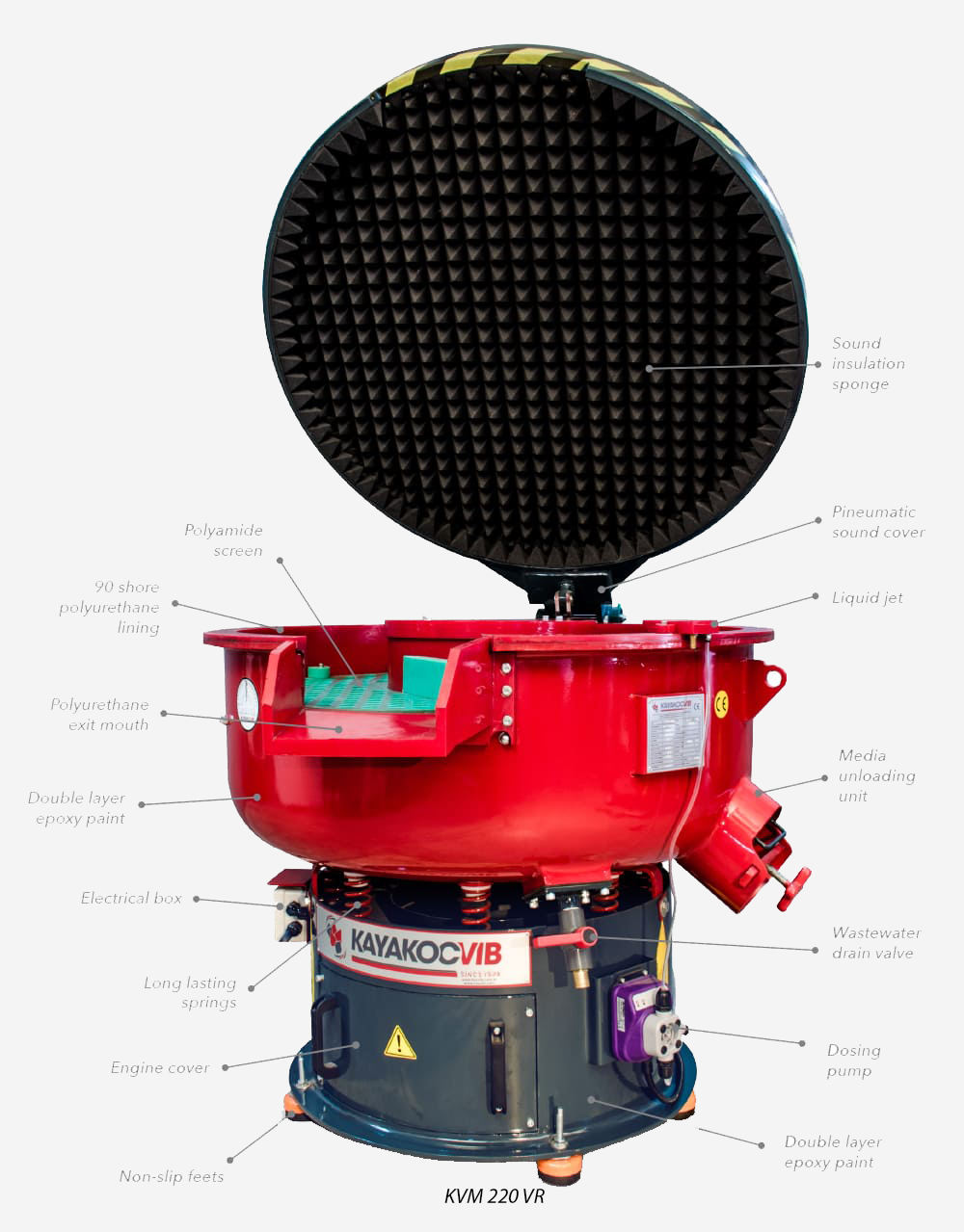
For production environments where scratches in vibratory finishing have been a persistent problem, machine selection should be reviewed as part of the optimization effort. Circular vibratory machines such as the KAYAKOCVIB KVM series are well-suited for small to medium parts requiring general deburring and polishing. The toroidal flow pattern provides consistent media coverage for most part geometries.
For long components, flat stamped parts, or geometries prone to part-on-part alignment, trough-type vibratory machines such as the KAYAKOCVIB TVM series may provide better control over part orientation and contact distribution. The linear flow path in a trough machine can reduce the tendency of elongated parts to align and slide against each other.
For precision parts with strict surface quality requirements where conventional vibratory finishing continues to produce scratch defects despite parameter optimization, centrifugal disc finishing machines may be a more suitable technology. Centrifugal disc machines operate at higher relative velocity but with more controlled and uniform contact geometry, which can reduce the random scratch risk present in conventional vibratory bowl operation.
Prevention Checklist for Ongoing Production Control
Preventing scratch defects from recurring requires consistent process discipline across the production team. The following checklist covers the main control points for ongoing scratch prevention in vibratory finishing operations.
- Verify media type is correctly matched to part material before each production run
- Inspect media condition at regular intervals and remove broken or severely worn pieces
- Confirm compound dosage rate and water flow at the start of each shift
- Check media-to-part ratio against validated process parameters before loading
- Segregate batches strictly by material type, never mix dissimilar metals
- Review machine amplitude and frequency settings against the process validation record
- Inspect first-off parts from each batch before committing the full load to production
- Document any change to media type, compound, water quality, or machine settings and validate before release
Frequently Asked Questions
Can the same vibratory machine process both aluminum and steel parts?
Yes, but not in the same batch. Aluminum and steel must always be processed in separate batches because steel parts will scratch aluminum surfaces due to the hardness difference. The machine can be used for both materials if it is cleaned between batches and the media, compound, and parameters are adjusted appropriately for each material.
Why do scratches appear only on certain parts within a batch?
Position within the batch affects contact intensity. Parts that consistently sit near the bowl wall or at the bottom of the load may receive different contact dynamics. This typically indicates a loading volume issue or media distribution problem. Reducing batch size or adjusting the machine amplitude can help distribute contact more evenly across all parts.
Does longer cycle time always improve surface finish?
No. Beyond the point where the required deburring or polishing result is achieved, continued operation causes media breakdown and can introduce fine scratching from increasingly sharp abrasive fragments. Cycle time must be validated against the surface quality target and not extended beyond the process window without retesting.
When should plastic media be used instead of ceramic media?
Plastic media should be the default choice for soft or sensitive materials including aluminum, zamak, copper, and brass. Ceramic media is typically reserved for steel, stainless steel, and harder materials requiring aggressive burr removal. When surface scratch sensitivity is a concern even on steel parts, a finer ceramic media grade or a burnishing process step may be more appropriate than a coarse cutting ceramic.
Related Process Equipment
Conclusion
Scratches in vibratory finishing are a diagnosable and correctable defect class. The root causes are well-defined and fall into consistent categories: wrong media type, insufficient compound, overloaded batches, mixed materials, worn media, or incorrect machine parameters. Each cause produces a recognizable symptom pattern that guides the corrective action. Addressing scratch defects effectively requires a systematic diagnostic approach rather than random parameter changes. For production engineers managing CNC machined parts, automotive components, or precision fasteners, the combination of correct media selection, calibrated compound flow, controlled loading ratios, and validated machine settings provides the foundation for consistent, scratch-free surface finishing results. Actual process capability must always be confirmed through sample testing before production release, as part geometry, material hardness, and batch composition all affect the final outcome.
Sorry, the comment form is closed at this time.