
26 Jun PLC Surface Finishing System
A PLC surface finishing system is the control backbone of any automated deburring, polishing, or mass finishing line. When this control layer is correctly engineered and maintained, it produces repeatable surface quality with minimal operator input. When it is poorly configured or degraded over time, the result is inconsistent cycle times, surface defects, compound overdosing, media imbalance, or unplanned downtime. Understanding how PLC control behaves in a surface finishing environment, and where it typically fails, is essential for process engineers responsible for finishing line performance.
In This Article
How PLC Control Functions in a Finishing Line
A programmable logic controller in a surface finishing application manages sequential machine states. These include bowl or trough vibration start and stop, compound dosing valve timing, water flow control, separator gate actuation, conveyor handoff, drying cycle activation, and safety interlock logic. In a multi-machine line, the PLC also handles part transfer coordination between the finishing machine, separation unit, washing station, and dryer.
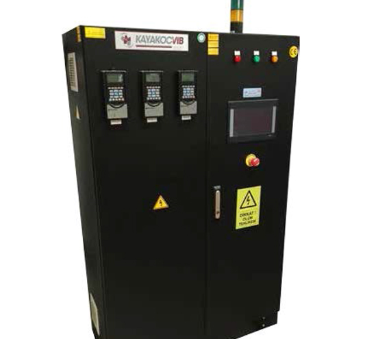
The control architecture typically consists of a central PLC connected to distributed I/O modules mounted near each machine section. Sensors feed the PLC with bowl load status, motor current draw, water level, temperature, compound tank level, and conveyor position signals. The PLC evaluates these inputs against stored program logic and issues output commands to actuators such as variable frequency drives, solenoid valves, servo motors, and indicator lights.
In modern installations, the PLC surface finishing system is often connected to an HMI touchscreen that allows operators to select recipes, monitor live process data, adjust cycle times, and respond to fault alarms. Recipe management allows the same machine to run different parts with different process parameters by recalling stored programs rather than manually adjusting settings.
Common Symptoms of PLC Control Problems
Control-related problems in surface finishing lines often appear first as surface quality variation rather than hard machine faults. Operators may notice that one batch produces a brighter surface finish than the next, or that some parts show residual burrs while others from the same load do not. These inconsistencies frequently trace back to the control layer rather than the media or machine itself.
Typical symptoms that indicate a PLC control issue include:
- Cycle time variation between shifts without process recipe changes
- Compound dosing that runs shorter or longer than programmed, resulting in foam buildup or dry running
- Parts exiting the finishing machine before the programmed cycle completes due to a separator gate fault
- Irregular bowl vibration intensity caused by incorrect VFD frequency commands
- Washing station not activating at the correct point in the sequence
- Dryer not reaching target temperature before parts arrive due to timing offset in the line sequence
Each of these symptoms has a distinct root cause category. Diagnosing them correctly requires understanding which part of the PLC program or hardware is involved.
Root Cause Categories for Control Failures
Control failures in a PLC surface finishing system fall into four main categories: hardware faults, programming logic errors, sensor drift or failure, and communication loss.
Hardware faults include relay contact wear, solenoid valve coil failure, corroded I/O terminals, and power supply instability. These are common in finishing environments because compound mist, vibration, and humidity accelerate electrical component degradation. Relay contacts used for compound dosing valves are particularly susceptible because they cycle many thousands of times per shift.
Programming logic errors are often introduced during recipe modifications or machine upgrades. A poorly structured conditional branch in the sequence program can cause a timer to reset incorrectly, a valve to stay open a few seconds longer than intended, or a machine to skip a process step under specific load conditions. These errors are difficult to detect without a controlled comparison between the intended and actual machine behavior.
Sensor drift is a slow-developing problem. A flow meter that reads consistently five percent low will cause compound concentration to fall over time without triggering an alarm. A proximity sensor with a slightly shifted mounting position may give false-positive part-present signals, causing the separator gate to open prematurely. Level sensors in compound tanks can accumulate residue that causes them to read incorrectly.
Communication loss between the PLC and remote I/O modules or between the PLC and the HMI can cause the machine to fall into a safe-state default mode that pauses production or runs a reduced sequence without alerting the operator clearly.
Machine Loading and Motion-Related Control Issues
Bowl loading affects the electrical load on the vibratory drive motor. If the PLC monitors motor current as a load proxy, an overloaded bowl will cause the VFD to reduce output frequency to protect the motor, which directly reduces finishing intensity. In a correctly engineered system, the PLC should alert the operator when motor current exceeds the calibrated load range rather than silently reducing intensity.
In drag finishing machines such as the KAYAKOCVIB DRG series, PLC control governs both the spindle rotation speed and the bowl rotation speed independently. If these two parameters drift out of synchronization due to a VFD parameter error or encoder fault, the relative velocity between the part and media changes, which affects material removal rate and surface finish quality. Any calibration change to either axis must be reflected in the stored recipe to prevent inconsistency.
For circular vibratory finishing machines, bowl amplitude is set by the eccentric weight configuration on the vibratory motor, but the PLC controls the running time and the compound dosing rate. If a machine is running with a partially blocked compound line and the PLC has no flow verification sensor, the program will assume dosing is occurring normally while the bowl is running essentially dry. This leads to media wear acceleration and inconsistent surface quality.
Compound Dosing Control Optimization
Compound dosing is one of the most directly PLC-controllable variables in a finishing line and also one of the most commonly miscalibrated. The correct dosing rate depends on bowl working volume, media type, part material, and the required surface finish. These values should be validated during initial process development and stored as part of the machine recipe.
A well-structured PLC dosing program will include a pre-wet phase at cycle start to condition the media and parts, a steady-state dosing phase during the main finishing interval, and a rinse phase near cycle end to flush residual compound from parts before separation. If the pre-wet phase is skipped or too short, compound distribution across the bowl will be uneven at the start of the cycle, which can cause inconsistent surface results across the load.
When troubleshooting compound-related surface quality issues, the first check should always be the actual dosing volume measured at the bowl inlet against the programmed setpoint. Valve wear, line restrictions, and pump calibration drift are all common causes of dosing deviation that the PLC cannot detect without a feedback flow sensor.
Parameter Tuning for Consistent Surface Quality
Optimizing a PLC surface finishing system for consistent output requires systematic parameter validation rather than empirical adjustment. The following parameters should be reviewed when surface quality inconsistency is detected:
| Parameter | Typical Control Point | Common Error |
|---|---|---|
| Finishing cycle time | PLC timer | Timer reset by alarm acknowledgment shortens actual run time |
| Compound dosing rate | Solenoid valve duty cycle or pump speed | Valve wear causes actual flow to fall below setpoint |
| Water flow rate | Flow control valve or solenoid | Pressure variation in supply line causes inconsistent flow |
| VFD output frequency | Analog output from PLC | Calibration offset causes actual frequency to deviate from recipe value |
| Separator gate timing | PLC output relay | Contact wear causes delayed actuation, extending effective cycle time |
| Dryer temperature setpoint | PLC analog output to heater controller | Setpoint not matched to part throughput rate, causing incomplete drying |
Each parameter should be verified against actual measured output, not only against the programmed setpoint. Logged production data from the HMI can help identify whether deviations are random or systematic, which guides corrective action.
Prevention Checklist for PLC Control Reliability
The following checks reduce the probability of control-related surface quality problems in a finishing line:
- Verify all sensor calibrations against known references on a scheduled basis, not only after fault events
- Confirm compound dosing flow rate at the bowl inlet quarterly using a timed volume measurement
- Review PLC program change history before investigating quality deviations, particularly after machine maintenance
- Check VFD parameter settings after any drive replacement, as factory defaults may differ from process requirements
- Inspect compound line filters and dosing valve seats for wear or residue buildup at every major maintenance interval
- Confirm that recipe recall correctly loads all parameters, including analog setpoints, not only timer values
- Test separator gate actuation timing with a stopwatch periodically to confirm relay contact integrity
- Verify communication integrity between PLC and remote I/O after any panel work or network change
Integrating PLC Control with Upstream and Downstream Processes
A finishing line PLC rarely operates in isolation. In integrated production environments, the finishing line PLC may receive part arrival signals from a CNC machining cell, or it may send completion signals to a downstream inspection or packaging station. Signal handoff errors between systems are a common source of line stoppages that appear as finishing machine faults but originate in the integration layer.
When a washing station is part of the finishing line, the PLC must coordinate part transfer timing with the washing cycle. Parts that arrive at the washing station before the wash cycle is ready will queue incorrectly. In pressure washing applications, the PLC must also manage pump startup sequencing and nozzle manifold activation to prevent pressure surges that can damage delicate parts.
In complete KAYAKOCVIB automation systems, the finishing machine, separator, dryer, and washing station operate under a coordinated line PLC that manages all transfer sequences and monitors process states across the full line. This architecture reduces the risk of independent machine timing causing parts to accumulate incorrectly between stations.
Frequently Asked Questions
What causes cycle time variation in a PLC-controlled finishing machine?
The most common causes are timer resets triggered by alarm acknowledgments, incorrect recipe recall, and VFD frequency deviations that alter machine energy delivery without changing the programmed run time. Sensor drift in load monitoring systems can also cause the PLC to end cycles early if a low-load condition is incorrectly detected.
How can compound overdosing be diagnosed in a PLC surface finishing system?
Compare the programmed dosing valve open time and duty cycle against the actual volume delivered at the bowl inlet using a timed measurement. If the measured volume exceeds the setpoint, check for valve seal wear that causes the valve to remain partially open after the close command, or check if a parallel dosing path has been left open manually.
What is the correct approach to recipe management in a finishing line PLC?
Each product recipe should store all relevant process parameters including cycle time, VFD frequency, compound dosing rate, water flow setpoint, separator gate timing, and dryer temperature. Recipes should be version-controlled, and any parameter change should be logged with a timestamp and operator identifier. Running undocumented manual overrides alongside stored recipes is a common source of unexplained quality variation.
Can PLC control compensate for worn finishing media automatically?
Standard PLC control cannot detect media wear directly. Media condition must be assessed manually by trained operators based on visual inspection, measured cutting performance, and surface roughness verification on sample parts. Some advanced installations use motor current trending over time to infer media degradation indirectly, but this approach requires careful baseline calibration and does not replace physical media inspection.
Related Process Equipment
Related Video Demonstration
Conclusion
Optimizing a PLC surface finishing system requires treating the control layer as an active process variable, not a fixed infrastructure element. Control hardware degrades, sensor calibrations drift, program logic accumulates undocumented changes, and communication paths develop latency over time. Each of these factors can produce surface quality inconsistencies that are indistinguishable from media, compound, or machine mechanical problems without a structured diagnostic approach. Engineers responsible for finishing line performance should audit control parameters with the same rigor applied to media selection and compound concentration. When the PLC surface finishing system is correctly maintained and validated, it delivers the process repeatability that high-volume deburring, polishing, and surface treatment operations depend on.
Sorry, the comment form is closed at this time.