
04 Jun Sedimentation Tank Surface Finishing
The sedimentation tank is one of the most functionally important components in a sedimentation tank surface finishing system, yet it is frequently underspecified during line commissioning. In vibratory finishing operations, process water carries a continuous load of abraded metal fines, spent compound residues, and suspended solids. Without a properly designed sedimentation and water treatment stage, these contaminants either re-enter the process and degrade surface quality or are discharged as untreated effluent, creating both environmental and regulatory problems. This article explains how sedimentation tanks work in vibratory finishing lines, how to size and operate them correctly, and how they integrate into closed-loop water recycling systems used in automotive, CNC machining, and general metal processing facilities.
The Role of Sedimentation in Vibratory Finishing Water Management
Vibratory finishing machines consume process water continuously during wet finishing operations. Compound dissolved in water acts as a lubricant, corrosion inhibitor, and surface activator throughout the cycle. As the process runs, water picks up metallic fines abraded from the workpiece surface, broken media particles, compound breakdown products, and in some applications, tramp oils or cutting fluid residues carried in with the parts.
If this contaminated water is discharged directly to drain after each cycle, the facility faces high water consumption costs, compound waste, and potential non-compliance with local effluent discharge limits. Sedimentation is the primary separation stage that allows this water to be clarified and returned to the process, recovering compound value and reducing freshwater demand.
The sedimentation tank provides the physical residence time and settling geometry needed for suspended solids to fall out of the water column under gravity. Clarified water is then returned to the vibratory machines or a clean water buffer tank, while accumulated sludge is periodically removed and disposed of as industrial solid waste.
How a Sedimentation Tank Works in a Finishing Line
Process water exits the vibratory finishing machine during and after each cycle through a drain or overflow outlet. This water flows into the sedimentation tank by gravity or through a pump. Inside the tank, the flow velocity drops significantly as the water spreads across a larger cross-section, allowing suspended particles to settle toward the tank floor.
Effective sedimentation depends on several physical factors: particle size and density, water temperature, flow rate through the tank, and tank geometry. Heavy metallic fines settle relatively quickly. Fine abrasive particles and colloidal compounds settle more slowly and may require additional treatment such as flocculation to aggregate fine particles into larger, faster-settling flocs.
A basic sedimentation tank for a single vibratory machine typically includes an inlet baffle to reduce turbulence, one or more settling chambers, an overflow weir for clarified water discharge, and a sludge collection zone at the base. More advanced configurations use inclined plate settlers or lamella separators to increase the effective settling area within a compact footprint, which is useful in production environments where floor space is limited.
Clarified water exits over the weir and flows into a clean water holding tank or is pumped directly back to the finishing machine water supply. Sludge accumulates at the bottom of the sedimentation chamber and must be removed at regular intervals, either manually or through an automated sludge pump and dewatering unit.
Closed-Loop Water Recycling in Vibratory Finishing Lines
A properly designed sedimentation tank surface finishing system can recover a high proportion of process water for reuse, reducing freshwater consumption to makeup water only. In a closed-loop configuration, water flows from the vibratory machine to the sedimentation tank, through the settling chamber, and back to the machine without discharging to drain during normal operation.
The practical effectiveness of this loop depends on the balance between solids loading and settling capacity. If the machine is running abrasive media on steel parts at high throughput, the solids loading is heavy and the sedimentation tank must be sized accordingly. Undersized tanks will carry over suspended solids into the return water, which re-enters the machine and can cause accelerated media wear, inconsistent surface results, or contamination of parts intended for high-finish applications.
Compound concentration in the recycled water also requires management. As water is recycled, compound builds up incrementally and fresh compound is added in controlled doses to maintain the correct working concentration. Conductivity monitoring or periodic titration is used in more controlled installations to track compound levels. Overflow or bleed-off of a controlled volume from the system prevents excessive compound buildup over time.
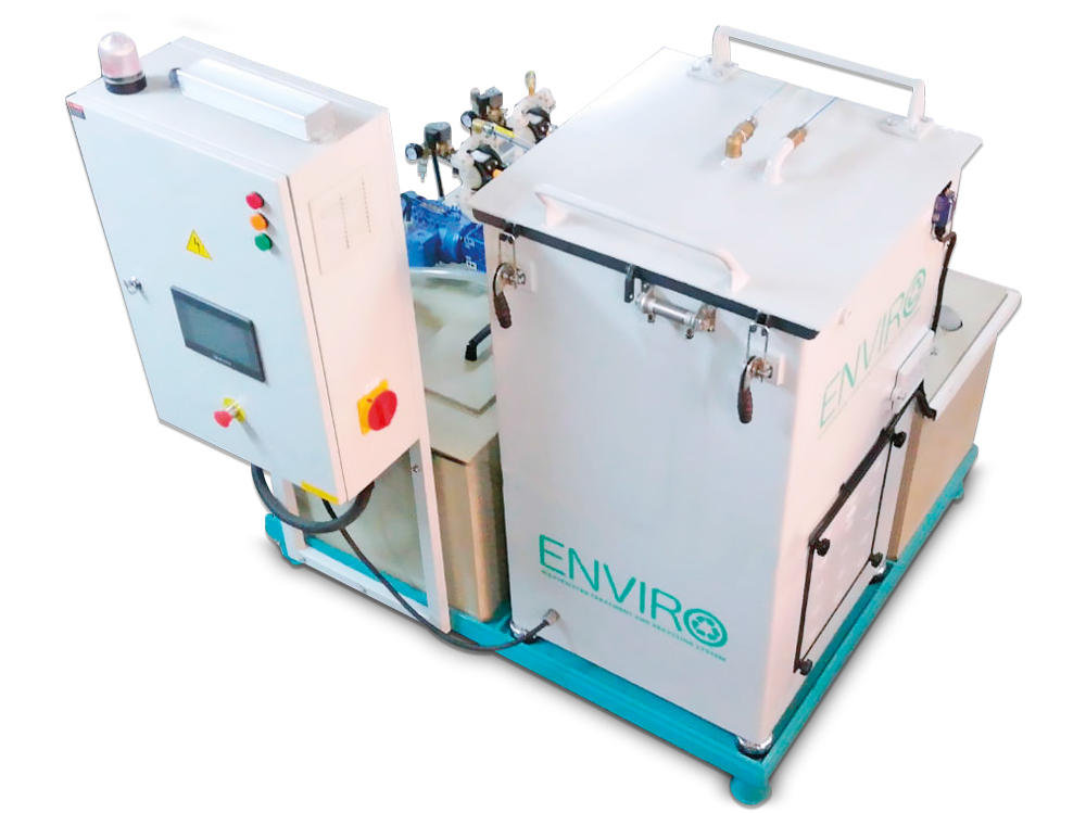
KAYAKOCVIB ENVIRO series wastewater treatment systems are designed around this closed-loop logic, combining sedimentation, compound dosing control, and clean water return in an integrated unit suitable for single-machine or multi-machine finishing lines.
Step-by-Step Process Flow in an SDM-T Sedimentation System
The following sequence describes the typical water management process flow when an SDM-T type sedimentation tank is integrated with a vibratory finishing line.
- Process water and compound are introduced into the vibratory finishing machine at the start of the finishing cycle. The compound dissolves and activates within the water to provide the correct finishing chemistry.
- During the finishing cycle, contaminated water carrying metal fines, abrasive particles, and compound residues flows continuously or in batch from the machine drain into the sedimentation tank inlet.
- Inside the SDM-T tank, an inlet baffle deflects the incoming flow downward, reducing surface turbulence and promoting laminar settling conditions in the main settling chamber.
- Suspended solids settle by gravity toward the sludge collection zone at the base of the tank. The settling time required depends on particle size and density. For fine particles, a flocculating agent may be dosed at the inlet to accelerate settling.
- Clarified water rises above the settled sludge layer and overflows the weir into the clean water compartment. From this compartment, a pump returns the water to the machine water supply tank or directly to the machine inlet.
- Fresh compound is dosed into the return water or directly into the machine on a timed or volume-triggered basis to maintain the correct compound concentration in the recycled water.
- Sludge accumulated at the base of the settling chamber is removed periodically using a sludge drain valve, pump, or automated sludge extraction system. The removed sludge is collected in a sludge container or passed through a filter press or dewatering bag for volume reduction before disposal.
- The system operates continuously as long as the finishing machine is running, maintaining a consistent water quality level in the closed loop without requiring batch water changes between production cycles.
Oil Separation and Flocculation in Finishing Wastewater
In many industrial environments, parts arriving at the finishing machine carry residual cutting oils, hydraulic fluids, or coolant from prior machining operations. These tramp oils enter the process water and float on the sedimentation tank surface, forming a separate oil layer that can interfere with the settling process and potentially contaminate recycled water if not removed.
Oil skimmers are commonly integrated into sedimentation tanks for finishing lines processing machined steel or aluminum parts. A belt skimmer, disc skimmer, or weir-type oil separator draws the floating oil layer away from the water surface continuously and collects it in a separate container for disposal. This prevents oil from re-entering the recycled water and maintains acceptable compound performance.
Flocculation is used when the process generates a significant fraction of very fine particles that do not settle within the available residence time. A flocculating agent, typically a polyelectrolyte or inorganic coagulant such as aluminum sulfate, is dosed into the incoming dirty water stream and mixed briefly before the water enters the settling chamber. The flocculant causes fine particles to bind together into larger aggregates that settle much more rapidly than the individual fine particles. The result is significantly cleaner overflow water and a denser sludge layer that is easier to dewater.
The KAYAKOCVIB FLOG flocculation dosing system automates flocculant addition based on flow rate or turbidity monitoring, removing the need for manual dosing and improving consistency across production shifts.
Sizing a Sedimentation Tank for a Vibratory Finishing Line
Correct tank sizing is the most important engineering decision in sedimentation system design. An undersized tank will carry over solids into the return water, while an oversized tank wastes floor space and capital. The key sizing parameters are total water volume in the system, peak flow rate from the finishing machine, required hydraulic residence time, and solids loading rate.
Hydraulic residence time is the average time a volume of water spends inside the settling chamber before exiting over the weir. For typical finishing wastewater with a mix of metallic fines and abrasive particles, residence times of 20 to 60 minutes are commonly used depending on particle size distribution and target overflow clarity. Lines processing very fine media or fine grinding compounds may require longer residence times or supplemental lamella separators.
The table below summarizes typical sizing considerations for sedimentation tanks in vibratory finishing applications.
| Parameter | Typical Range | Engineering Note |
|---|---|---|
| Hydraulic residence time | 20 to 60 minutes | Longer for fine particles or high-clarity requirements |
| Tank working volume | 2x to 4x machine water volume | Must accommodate surge flow during drain cycles |
| Sludge cleaning interval | Daily to weekly | Depends on part material and media abrasivity |
| Flocculant dosing | Application-specific | Required for fine particles below 10 micron |
| Oil skimmer | Recommended for machined parts | Essential if parts carry cutting oil into the process |
For multi-machine finishing lines with multiple vibratory units sharing a common water treatment system, the sedimentation tank must be sized for the combined flow from all machines running simultaneously. A common clean water buffer tank between the sedimentation unit and the machine supply pumps reduces the sensitivity of the system to flow rate variations during machine drain cycles.
Process Parameters That Affect Sedimentation Performance
Several process variables directly influence how well a sedimentation tank performs in a finishing line. Water temperature affects fluid viscosity, which in turn affects settling velocity. Warmer water is less viscous and allows faster settling, while cold water slows the process. In environments where water temperature drops significantly in winter, this must be accounted for in residence time calculations.
Inlet flow rate and turbulence are equally important. If dirty water enters the tank too fast or without a proper baffle, it creates turbulent currents that disturb the settled sludge layer and carry fine particles into the overflow. A correctly designed inlet zone with a baffle plate and flow diffuser is not optional engineering detail but a functional requirement for reliable sedimentation.
Compound type also affects performance. Some finishing compounds produce stable foam or colloidal suspensions that resist settling. In these cases, defoaming agents or a change in compound formulation may be needed to achieve acceptable overflow water quality. This interaction between compound chemistry and sedimentation behavior should be evaluated during process setup, not after the line is in production.
Integration with Automated Vibratory Finishing Lines
In automated finishing lines where multiple vibratory machines run continuously across multiple shifts, the sedimentation tank becomes a central infrastructure element rather than a peripheral accessory. A well-integrated water treatment circuit allows the line to operate with consistent water quality throughout the production day without requiring manual water changes or operator intervention.
PLC-controlled sedimentation systems can automate flocculant dosing, sludge pump activation based on level sensors, compound dosing triggered by conductivity measurement, and alarm outputs for high turbidity or low clean water level. This level of automation reduces labor requirements, improves water quality consistency, and creates a traceable record of water management conditions linked to production batches.
The sedimentation tank surface finishing water circuit can also be integrated with separator machine drain lines, washing system rinse water returns, and drying machine condensate recovery, creating a unified water management infrastructure across the entire finishing line rather than treating each stage independently.
Frequently Asked Questions
What size sedimentation tank is needed for a single vibratory finishing machine?
A common starting point is a tank working volume of two to four times the water volume of the vibratory machine, with hydraulic residence time of at least 30 minutes at peak flow. The exact size depends on the solids loading rate, part material, media type, and target water clarity. Final sizing should be validated during commissioning.
Can a sedimentation tank handle oil-contaminated finishing water?
Yes, but an oil skimmer must be included to remove floating oil from the tank surface. Without active oil removal, tramp oils can accumulate, interfere with compound performance, and contaminate recycled water. Belt or disc skimmers are the most commonly used configurations in finishing line applications.
When is flocculation necessary in a sedimentation system?
Flocculation is typically necessary when the finishing process generates very fine particles that do not settle within the available residence time, or when overflow water clarity is insufficient despite adequate residence time. This is common in fine grinding, polishing, and stainless steel finishing applications where submicron particles are generated.
How often does sludge need to be removed from a sedimentation tank?
Sludge removal frequency depends on solids loading. Heavy production lines finishing steel or cast iron parts may require daily sludge removal, while lighter-duty applications may require only weekly cleaning. Sludge level sensors or regular manual inspection determine the appropriate interval for each installation.
Conclusion
A sedimentation tank is not a passive accessory in a vibratory finishing line. It is an active process element that directly affects water quality, compound efficiency, surface finishing consistency, and regulatory compliance. Proper sizing, inlet design, oil separation, flocculant treatment where needed, and sludge management are all engineering decisions that determine whether the closed-loop water system performs reliably across production shifts. For facilities running high-throughput vibratory finishing lines across automotive, CNC machining, or general metal processing applications, investment in a correctly specified sedimentation tank surface finishing circuit delivers measurable reductions in water consumption, compound cost, and wastewater disposal volume. The actual performance of any sedimentation system depends on part material, media type, compound chemistry, and flow conditions, and should be validated through a trial period with process monitoring before full production release.
Sorry, the comment form is closed at this time.