
03 Jun Size Surface Finishing Line
To size a surface finishing line correctly, engineers must translate production volume requirements into concrete machine capacity, cycle time targets, and automation configurations before specifying any equipment. A line that is undersized creates bottlenecks, while an oversized line wastes capital and floor space. The decisions made during line sizing directly affect throughput, part quality consistency, labor cost, and the ability to scale production in the future.
Starting Point: Define the Production Volume Requirement
Before selecting any machine, the engineering team must establish the baseline numbers. This means calculating the required throughput in parts per hour or kilograms per hour, identifying the number of production shifts, and understanding whether the line must handle one part family or multiple different geometries and materials.
The following parameters form the input data set for any line sizing calculation:
- Total annual or monthly production quantity by part type
- Number of working shifts and available hours per shift
- Average part weight and volume
- Batch size if batch processing is used, or feed rate if continuous processing is planned
- Required surface finish outcome, such as edge rounding radius, Ra target, or deburring specification
- Part material and sensitivity to mechanical contact or heat
Once these values are defined, engineers can calculate the required machine output rate and compare it against machine working volume and typical cycle time for the selected process.
Capacity Calculation Logic for Batch Finishing
Most vibratory finishing machines operate in batch mode. The machine is loaded, runs for a defined cycle time, and then discharged and separated. Capacity planning for batch machines follows this calculation structure:
Required batches per shift = (parts required per shift) divided by (parts per batch). The parts per batch is determined by the machine working volume and the recommended load ratio, which is typically 50 to 80 percent of the working volume depending on part geometry and media-to-part ratio requirements.
Cycle time is one of the most critical variables. For light deburring of CNC-machined aluminum parts, a typical cycle in a circular vibratory machine may range from 30 to 90 minutes depending on burr size, media type, compound aggressiveness, and required Ra improvement. For heavier steel parts with larger burrs, cycle time may extend significantly. For high-speed centrifugal disc finishing, cycle times are often much shorter, sometimes in the range of 5 to 20 minutes, making this technology more suitable where short cycle times are needed to meet volume.
When planning capacity, always include non-process time such as loading, separation, washing, drying, and inspection. These steps add to the total cycle and must be accounted for when sizing the full line, not just the finishing machine itself.
Machine Type Selection Based on Part and Volume Profile
Machine selection drives the capacity and footprint of the entire finishing line. The part geometry, material, required finish, and production volume all influence which machine type is appropriate.
| Machine Type | Best Suited For | Typical Cycle Time Range | Automation Compatibility |
|---|---|---|---|
| Circular Vibratory (KVM) | Small to medium parts, mixed batches, general deburring and polishing | 30 to 120 minutes | High — conveyor, separator, dryer integration |
| Centrifugal Disc (KSM) | Small precision parts, high volume, short cycle requirement | 5 to 25 minutes | Medium to high |
| Trough Vibratory (TVM) | Long parts, large components, delicate parts requiring gentle action | 30 to 150 minutes | Medium |
| Drag Finishing (DRG) | High-precision parts, cutting tools, medical implants, mold surfaces | 10 to 60 minutes | Low to medium |
For most CNC machining, automotive, fastener, and general manufacturing applications, circular vibratory finishing machines are the most common choice for line sizing because they offer good volume capacity, reliable media-to-part contact, and straightforward integration with downstream separation and drying equipment.
For applications with very high throughput requirements and small part sizes, centrifugal disc finishing may deliver shorter cycle times, allowing a smaller machine to match the same output as a larger vibratory machine. The tradeoff is higher process intensity, which requires careful evaluation for thin-walled or fragile parts.
How to Size Surface Finishing Line Components Beyond the Main Machine
The finishing machine is only one element of the line. When sizing a surface finishing line for production volume, every downstream station must be sized to match or exceed the output rate of the finishing machine. A common mistake is selecting the correct finishing machine but underspecifying the separator, dryer, or washing station, which then becomes the bottleneck.
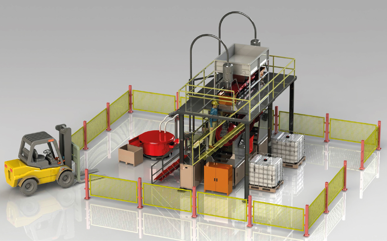
A typical automated finishing line includes these sequential stations:
- Part loading or feed system — manual, conveyor, or robotic
- Finishing machine — vibratory, centrifugal disc, or drag finishing
- Part-media separator — vibrating screen or rotary separator matched to the machine output
- Washing station — to remove compound residue, chips, and media fines from the part surface
- Drying unit — hot air dryer or corn cob drying machine matched to part throughput
- Inspection or transfer conveyor
- Compound and water dosing system — automatic dosing ensures consistent chemistry
Each station must be matched to the throughput of the finishing machine. For a circular vibratory machine such as the KAYAKOCVIB KVM series, the separator and dryer are selected based on the machine working volume and expected discharge rate per batch. If two machines are running in parallel to meet volume, two separators or one larger separator capable of handling dual input must be specified accordingly.
Process Parameters That Affect Line Throughput
When sizing a finishing line, it is not sufficient to count machines. The process parameters that control cycle time and surface quality must also be defined, because they directly determine how many batches per shift the line can complete.
Key parameters include:
- Media type and size — smaller media increases contact points but may extend cycle time for heavy deburring; larger media removes material faster but may miss internal features
- Compound concentration and flow rate — affects surface chemistry, foam level, and cleaning efficiency during the process
- Vibration amplitude and frequency — higher amplitude increases process intensity and can shorten cycle time but increases part-on-part impact risk
- Water flow rate — continuous water flow carries away swarf and maintains stable compound concentration; insufficient water flow causes slurry buildup and unpredictable surface results
- Media-to-part volume ratio — typically 2:1 to 4:1 depending on part geometry; too little media causes part damage; too much media reduces effective contact
- Batch load weight — overloading reduces media mobility and extends cycle time; underloading wastes machine capacity
For steel and stainless steel parts, abrasive ceramic media with an appropriate cutting compound is commonly selected. For aluminum, plastic or ceramic media with neutral or mildly abrasive compounds is preferred to control material removal rate and avoid surface contamination between dissimilar metals. Aluminum and steel parts should not be processed in the same batch.
Parallel Machines Versus Larger Single Machines
When production volume exceeds the capacity of one machine, engineers must decide between installing one large machine or running two or more smaller machines in parallel. Each approach has different implications for the finishing line layout and risk profile.
A single large machine simplifies the line layout, reduces the number of separators and dryers required, and makes PLC-based recipe management straightforward. However, if the machine requires maintenance or a process change, the entire line stops.
Two smaller machines running in parallel provide redundancy. If one machine is taken offline for media replacement or maintenance, the other continues running at 50 percent capacity. Parallel configurations also allow different part types or different process recipes to run simultaneously, which is useful in mixed-production environments serving automotive, aerospace, and fastener customers at the same time.
In high-volume automated lines, a common configuration uses two or three circular vibratory finishing machines feeding into one shared separator and dryer system with sufficient capacity to handle combined throughput. This balances capital cost with operational flexibility.
Automation Level and Its Effect on Line Sizing
The level of automation chosen during line design affects not only labor cost but also the physical sizing of the finishing line. Fully automated lines require consistent batch sizes, defined loading sequences, and integration of sensors, PLCs, and conveyor systems. This standardization reduces process variability, which in turn improves cycle time predictability and makes capacity planning more reliable.
For production volumes that require three or more shifts of continuous operation, automation becomes necessary to maintain consistent output and surface quality. Manual loading and unloading introduces variability in batch size, compound concentration, and cycle duration, which reduces the reliability of throughput estimates made during line sizing.
In automated KAYAKOCVIB finishing line configurations, automatic compound dosing systems, PLC recipe control, integrated separation, and hot air drying are combined into a single programmable line. This allows the finishing line to be sized accurately against shift requirements and production schedules, with documented process parameters that can be validated and repeated across shifts.
ROI Calculation When Sizing a Finishing Line
Sizing a surface finishing line also involves a financial justification, particularly when replacing manual deburring or when expanding an existing line. The return on investment depends on four main variables: labor cost reduction, throughput increase, scrap rate reduction, and energy and consumable efficiency.
A simplified ROI framework for a batch vibratory finishing line considers the following inputs:
- Current manual finishing cost per part — labor hours multiplied by hourly labor rate
- Expected machine throughput — parts per hour multiplied by available hours
- Machine investment cost including installation, media, compound, and integration
- Annual consumable cost — media replacement, compound, water, and energy
- Maintenance cost estimate per year
If a plant currently employs four operators for manual deburring at eight hours per shift and the machine can process the same quantity in two automated hours per shift, the labor saving alone can generate payback within one to three years in many industrial scenarios. Actual payback period depends on local labor rates, part complexity, and required surface quality. These estimates require site-specific validation and should not be treated as guaranteed outcomes.
Common Sizing Mistakes to Avoid
Several sizing errors consistently appear when engineers or procurement teams design finishing lines without sufficient process data:
- Sizing the machine to average production volume rather than peak volume, which causes the line to fall behind during high-demand periods
- Ignoring downstream station capacity — separator, washer, and dryer throughput must match the finishing machine output
- Using incorrect media-to-part ratio assumptions, which changes the effective batch size and shifts the capacity calculation
- Not accounting for media wear over time — as media wears, it changes size, contact behavior, and effective batch fill, which affects throughput and surface results
- Selecting a machine without considering future part mix changes — a line sized for one specific part family may not accommodate new geometries without significant modification
- Underestimating floor space and utility requirements — vibratory finishing machines require leveled floors, water supply, drain connections, and compound storage
Frequently Asked Questions
How do I calculate the number of machines needed for a given production volume?
Divide the required throughput in parts per hour by the parts per hour each machine can produce based on batch size and cycle time. Add a utilization factor of 80 to 90 percent to account for loading, separation, and maintenance time. If the calculation exceeds one machine’s capacity, add a second machine.
Can one finishing line handle multiple part types and materials?
Yes, but material segregation rules must be respected. Aluminum and steel should not be processed in the same batch. Different part geometries may require different media sizes or cycle times, which means recipe changeover time must be included in the line capacity plan.
What is a realistic media-to-part ratio for vibratory finishing?
A ratio of 2:1 to 4:1 by volume is common in most vibratory finishing applications. The correct ratio depends on part geometry, part weight, and the level of part protection needed. Parts with delicate features or thin walls typically require higher media ratios to cushion part-on-part contact.
When does automation become justified for a finishing line?
Automation is typically justified when the line runs more than two shifts, when labor cost is a significant portion of finishing cost, when surface quality consistency is a documented requirement, or when throughput exceeds what can reliably be managed manually without quality variation.
Conclusion
To size a surface finishing line for production volume, engineers must work through a structured calculation that connects required throughput to machine capacity, cycle time, downstream station sizing, and automation level. The finishing machine is the core of the line, but its capacity only delivers value if the separator, dryer, washing system, and compound dosing are matched to the same throughput target. Selecting machine type based on part geometry, material, and required finish — and then validating the line design against peak volume rather than average volume — is the foundation of a reliable finishing line. Process parameters including media selection, amplitude, compound concentration, and batch load weight must be defined before sizing is finalized, because they directly determine cycle time and therefore overall line output. Final process capability and throughput must always be confirmed through sample testing and process validation under actual production conditions.
Related KAYAKOCVIB Technical Resources
Related Video Demonstration
BCP10 automated blank coin polishing system example showing integrated polishing, separation, and drying logic for production line applications.
Sorry, the comment form is closed at this time.